4026 counter help 2 7-segments

Thread Starter

Dmm

Joined Apr 13, 2015
70
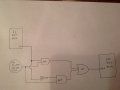
What I'm trying to accomplish is have (2) 4026B counters connected to (2) 7-seg. displays to show 0-99 values. I setup a test circuit and have it working with the carry out to increment the 10's value, using a push button and 555. With each segment controlled by a single 4026B using carry out. Now I am trying to add a new button/555 so I can increment the 10's with the new button/555 and also have the carry out increment when the 1's reset to zero. Is this possible?

Schematic I'm following is located here. I thought I could add a new button/555 and connect the pin 3 of this 555 to the clock on the 4026B...so that two wires are connected to the clock on the 10s digit, the carry out from the 1's and this button.

Bonus question, when I have the single button/555 "0-99" setup working, when I plug in the power it defaults to "10" value and not "00" value, any insight here? May have something to do with alligator clips I'm using on the power leads to the breadboard? Sometimes I can get it to "00" when connecting.
 

dl324

Joined Mar 30, 2015
16,909
[snip]Now I am trying to add a new button/555 so I can increment the 10's with the new button/555 and also have the carry out increment when the 1's reset to zero. Is this possible?

[snip]I thought I could add a new button/555 and connect the pin 3 of this 555 to the clock on the 4026B...so that two wires are connected to the clock on the 10s digit, the carry out from the 1's and this button.
You can do it, but you can't "wire-OR" the two signals; you need to use an OR gate. Do you care about cases where your two 10's increment signals happen at the same time? Do you want both to increment the count?
Bonus question, when I have the single button/555 "0-99" setup working, when I plug in the power it defaults to "10" value and not "00" value, any insight here?
You need to add logic to reset both counters when power is applied. A common approach is to use a schmitt NAND or inverter with a resistor and cap. The way it's wired in your reference schematic doesn't reset the counters.
 

Thread Starter

Dmm

Joined Apr 13, 2015
70
Thanks for the quick reply. I setup an OR gate similar to this step #7 using slightly different resistor values (8.2k and 4.7k) so my carry out from the 1s and the new button to "+10" go into the OR. This did not work. I thought maybe the resistors were too much and took out the 10k resistors and it did start working. A little quirk, the "adding 1" works and it carries out to "10" just fine, but the "add 10" button didn't work at first then it did. Not exactly sure what's going on. I wiggled the output wire from my OR to the 4026 controlling the 10s digit and sometimes that worked, but doesn't make too much sense as the 1's carry over signal (from the OR using same output wire) always worked. Maybe I just got very cheap jumpers and breadboard off internet or something.

When I have more time I will rebuild from scratch, try to get a schematic and verify all my resistor values, etc. I think that's the best next step for me, and anyone trying to help.

I did swap the 555 around and also the 4026 to see if it changed anything but it did not.
 

dl324

Joined Mar 30, 2015
16,909
Hi Dmm,

You don't have access to a CMOS (4071) or TTL (74*32) OR gate?

Do you have a logic probe? If not, they're easy to build and make troubleshooting slow logic circuits easier.
 

Thread Starter

Dmm

Joined Apr 13, 2015
70
I don't have any of those, just starting out with some hobby project ideas and learning a lot so far! I do have assortment of basic resistors, caps, transistors, LEDs. Will have to look at making a logic probe, looks like that would be handy.
 

dl324

Joined Mar 30, 2015
16,909
I don't have any of those, just starting out with some hobby project ideas and learning a lot so far!
Do you have any signal diodes? In this case, that's all you need. Put the two cathodes on the clock input to your second counter and drive the anodes with the two clock signals.

Here's something from circuitstoday.com:2-Input-Diode-OR-Gate.jpg

Make R1 10K. Want to try to explain how this works?

If you're just starting out, get some basic logic chips; they'll be easier to use than transistors. You can synthesize any gate you want from NAND gates.

If you build your own logic probe, you'll need one for CMOS and one for TTL because they have different threshold voltages. Ideally it will indicate HI, LO, and float.
 

Attachments

Last edited:

Thread Starter

Dmm

Joined Apr 13, 2015
70
I do not have any diodes, but made the OR in your picture with LEDs and I did get both the 1s with carry out working an also the "+10" button working at the same time/same circuit (my desired effect!)....for only a few button presses. The 1s with carry out still work every time but the "+10" button stopped working. I'm guessing the logic probe would help troubleshoot here. I couldn't get it working again wiggling wires as before. I tried disconnecting power for a while and reconnecting, and still can't get the +10 button to work. (Weird, now pressing a few mor buttons and the +10 works.)

Another interesting point, the LED connected to the carry out (through the OR gate) on the 1s 4026 is lit up when the 1s is 0-4 and the LED is off when the 1s is 5-9. I thought the carry out sent a short high pulse to the other 4026 to increment and I wouldn't be able to see the LED flash or see it flash just very briefly.

When both buttons (+1 w/carry out and +10) work, the LED (my diode in your OR gate picture) does briefly flash on the +10 button push. No matter what number the 10s is on. So the carry out works a little different than my 555 one shot button it seems.

And now after a few more button presses, think I found something interesting. When my 1s LED is lit up (1s at 0-4) the +10 button will not work. When my 1s LED is not lit (at 5-9) then the +10 button does work. Without wiggling any wires! We must be getting closer to the answer I suspect.

Am I using an incorrect 4026 for my desired effect maybe? I bought the mouser CD4026BE. And the 555s are mouser LM555CN.
 

dl324

Joined Mar 30, 2015
16,909
Hi Dmm,
I do not have any diodes, but made the OR in your picture with LEDs and I did get both the 1s with carry out working an also the "+10" button working at the same time/same circuit (my desired effect!)....for only a few button presses.
LEDs will work, but signal diodes will work better (in a pinch, you could also use the base-emitter or collector-base junction from a transistor). 1N4148 are very affordable, you should be able to get them for less than a few cents each (in qty 50+) even from Mouser. Can you explain why this works when wire-ORing won't? Can you think of any problems this could cause?
The 1s with carry out still work every time but the "+10" button stopped working.
Will address this later.
I'm guessing the logic probe would help troubleshoot here.
I became aware of them in the late 70's and still use them when it isn't convenient to hook up a scope.
Another interesting point, the LED connected to the carry out (through the OR gate) on the 1s 4026 is lit up when the 1s is 0-4 and the LED is off when the 1s is 5-9. I thought the carry out sent a short high pulse to the other 4026 to increment and I wouldn't be able to see the LED flash or see it flash just very briefly.
This is because the carry out signal is also a clock/10 square wave. The counter is positive edge triggered, so this is why your button pushes for the second counter only work when carry out is low.
 
Last edited:

Thread Starter

Dmm

Joined Apr 13, 2015
70
Try to answer some of your questions I have not addressed.
If both the +1 and +10 buttons are pressed at same time, for my application it doesn't matter if it counts 20 (or better put, the user can hit the +10 to get back on track) for example if count = 39 and they both send a signal at same time to count 1 and also count 10 to result in a count of 50. I do not desire to build a circuit to counter this problem. Chance is low and not detrimental to anything if it does happen.

Your question about the diode OR gate...and why I think the "wire OR gate" doesn't work...
I understand the diodes prevent current flowing backwards (cathode to anode.) this must be the key to the reason the "wire OR" doesn't work. If I had no prevention of current flowing from one input backwards to the other input, it leads me to believe (since it didn't work as anticipated) there was lower resistance between inputs than the path going into my 2nd 4026 therefore preventing the 10s to increment.
 

dl324

Joined Mar 30, 2015
16,909
Your question about the diode OR gate...and why I think the "wire OR gate" doesn't work...
I understand the diodes prevent current flowing backwards (cathode to anode.) this must be the key to the reason the "wire OR" doesn't work.
Very good.
If I had no prevention of current flowing from one input backwards to the other input, it leads me to believe (since it didn't work as anticipated) there was lower resistance between inputs than the path going into my 2nd 4026 therefore preventing the 10s to increment.
The OR function avoids problems with the two outputs fighting each other.
 

Thread Starter

Dmm

Joined Apr 13, 2015
70
So now to the issue of getting the +10 button working when the 1s digit is at 0-4. I'm guessing the reason the carry out goes from high to low at changing from 4-5 is it is "getting ready" for the next 10s increment, and it needs a little time to set itself up...or perhaps gives itself time if the clock is fast? Am I thinking about this correctly?
 

dl324

Joined Mar 30, 2015
16,909
So now to the issue of getting the +10 button working when the 1s digit is at 0-4. I'm guessing the reason the carry out goes from high to low at changing from 4-5 is it is "getting ready" for the next 10s increment, and it needs a little time to set itself up...or perhaps gives itself time if the clock is fast? Am I thinking about this correctly?
Look at page 3 of the attached datasheet. The carry out signal is a square wave that has a rising edge when the counter rolls over. If you want to be able to have your timer increment when the first digit is less than 5, you need to change how carry out is used to increment the 10's counter. Can you think of a way to do this?
 

Attachments

Thread Starter

Dmm

Joined Apr 13, 2015
70
Hmmm... Let's see.

Had to think a while but started looking more at logic gates. The timing diagram got me thinking there are two scenarios where I want to increment the 10s. One while the carry out is high and one where it is low. So:

(1) While carry out is high and 10s button is pressed, or high, then send high output to clock on 10s digit.
(2) While carry out is low and 10s button pressed, or high, then send high output to clock on 10s digit.

So on (1) I need AND gate so if both are high it outputs high, otherwise outputs low.
On (2) I need to output INVERT carry out...and then AND that output with the button press, if both these high send high, otherwise outputs low.

Then with these two paths outputs I need to use an OR. This output of the OR would go to the clock of my 10s digit.

I sketched out this logic circuit in the attached picture. Am I on the right path?
 

Attachments

dl324

Joined Mar 30, 2015
16,909
Hi Dmm,

Good try. That will work for all but the typical case where carry out needs to increment the 10's counter and the timer isn't trying to increment.

Can you think of a way to generate a pulse from carry out?
 
Last edited:

Thread Starter

Dmm

Joined Apr 13, 2015
70
Of course I neglected the "default operation"! Would I be able to add a 3rd segment where carry out is high AND button is low (invert similar to the one in sketch)...and then use another OR between this output and my last OR before the clock on my sketch? ... Now that I think about that, it's probably the same outcome I have now...since this 3rd logic I just described would be true or high from 0-4. So that won't work.

So back to your comment about the pulse. And now I think I should think of the carry out like a button press and use another 555 to get the pulse. Is that it!
 

dl324

Joined Mar 30, 2015
16,909
Hi Dmm,

This is what I had in mind:
os1.jpg

You already have the diodes (LEDs). Adding the R and C before Cout would create a positive pulse on it's rising edge. Then the cap would discharge and the anode of D1 would be at ground; allowing a rising edge from timer to generate a clock pulse.

The only problem is that you're using LEDs instead of signal diodes and their forward voltage, even at low currents, might cause enough voltage drop that the Cout pulse won't be able to generate a 3.5V pulse long enough for the counter to advance. This is one of the problems associated with using diodes for ORing. You give up a diode drop of noise immunity and it servers to increase the threshold voltage of the input being driven. LEDs compound the problem because they give twice the drop of a signal diode. If you're not already using red LEDs, use them if you have them; they tend to have the lowest Vf.

But you can give it a try. Here's where a logic probe would come in handy because it could tell you if there was a pulse at or above Vih(min).

Can you explain how the R and C will generate a pulse? And how to determine pulse width?
 
Last edited:

Thread Starter

Dmm

Joined Apr 13, 2015
70
This worked just as I wanted it to! Thank you for the help!

I do understand the timer (representing my button to increment by +10.) On the button press, it sends a pulse which is allowed to pass through the diode D1 and onto the clock (of my 10s digit 4026 counter.) The D2 prevents this pulse from "back flowing" into the capacitor. And the R2 is a higher resistance than going to the clock so it's forced to go to the clock. Is that a good way to think about the R2 as it is a high resistance compared to the path into the clock so the current flow doesn't want to go through R2?

Now when I think about the carry out signal working in this circuit, I get stumped. To me the carry out when the 1s digit is 0-4 has a high signal, not a pulse. So when it goes high, it charges the capacitor and allows current through. That was my thinking.

I wasn't sure how the pulse is generated. I read a little more on capacitors and it looks like as the voltage rises on the capacitor it allows a current across the capacitor. Then once the capacitor is fully charged and a constant voltage still being applied the current across the capacitor goes to zero. So the pulse is generated on the voltage going from 0 to say 5v of my supply. And once the capacitor is charged, the carry out still has a high signal but is constant and the current across the capacitor goes to zero.

Am I understanding this now?
 

dl324

Joined Mar 30, 2015
16,909
This worked just as I wanted it to! Thank you for the help!
Glad it worked. I was concerned about the voltage drop of the LEDs. When you get a chance, you should replace them with signal diodes. That will give you back some noise margin; and insure that the pulse generation will work reliably. Or better yet, replace the diodes with an OR gate.
I do understand the timer (representing my button to increment by +10.) On the button press, it sends a pulse which is allowed to pass through the diode D1 and onto the clock (of my 10s digit 4026 counter.) The D2 prevents this pulse from "back flowing" into the capacitor. And the R2 is a higher resistance than going to the clock so it's forced to go to the clock. Is that a good way to think about the R2 as it is a high resistance compared to the path into the clock so the current flow doesn't want to go through R2?
Actually the clock input looks like a higher impedance (resistance) than R2. R2 is used to develop the voltage that becomes the rising edge that increments the counter.
Now when I think about the carry out signal working in this circuit, I get stumped. To me the carry out when the 1s digit is 0-4 has a high signal, not a pulse. So when it goes high, it charges the capacitor and allows current through. That was my thinking.
When carryout transitions to HIGH, it causes both electrodes of the cap to "see" 5V (because the voltage across a cap can't change instantaneously). Capacitors can be treated as open circuit to DC (which is why caps are used to couple AC while ignoring any DC component of signals). Once the the cap is brought to 5V, it will start discharging according to the RC time constant of R1 times C1 which gives a time constant of 100uS. When that voltage is a diode drop (LED in your case) above Vih(min), that input is now considered "not HIGH" (but not low either) and it's ready to receive another rising edge. Eventually the cap discharges enough to be considered a LOW logic level.
 
Top