Facebook
 Google
 GitHub
 Linkedin
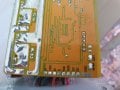
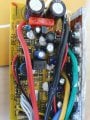
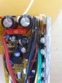
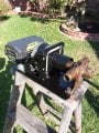
I have got it working. Connect the Yellow wire to the Brown wire this turns on the lights (and turns on the board?) When these are connected to the Black it starts up. Why there is the Red wire in this bundle I don't know. I still have to active the reed switch in the bag safety but that should be a easy rewire. The tilt sensor does not have to be there so that's great. I connected the motor to my pump and it works fine. Will it pump up to a 80 foot head I don't know. according to flow rate, head, and HP it should do it. Won't know until I get up to the cabin.
40 volt 3 wire brushless lawnmower motor
- Thread starter Demonsgirl
- Start date