I don´t understand why it wouldn´t work, as per my explanation I didn´t find any flaw. If you could please elaborate on your reply @djfantasi I would appreciate it.
You would operate each motor individually in the first two positions of the first switch and then moving the second switch to the connection of the desired motor
You would operate each motor individually in the first two positions of the first switch and then moving the second switch to the connection of the desired motor
I think I know what you mean @Ramussons. You are correct, you wouldn´t be able to run two or more motors simultaneously in different directions. Nevertheless, this is not really something I would need (I want one at a time or all at the same time), so both of the following schematics would work right?
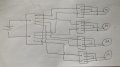
When you mentioned putting the dp4t on the left, did you refer to something like this? This would allow every motor to be selected individually, and put on forward and reverse, but not simultaneously. What do you suggest?
When you mentioned putting the dp4t on the left, did you refer to something like this? This would allow every motor to be selected individually, and put on forward and reverse, but not simultaneously. What do you suggest?
I´m trying to include the four tasks you mentioned, but it wouldn´t really work for individual powering with so many connections as the current would flow through one of the wires its not supposed to and power the other motor
I´m trying to include the four tasks you mentioned, but it wouldn´t really work for individual powering with so many connections as the current would flow through one of the wires its not supposed to and power the other motor
It certainly looks like the correct solution. I’m still unpacking from my vacation and doing laundry, so haven’t traced every option, but at first glance it looks like you’ve figured it out...
I’m a tiny bit OCD (a good trait for an engineer) so refrain from saying I’m 100% sure this is the correct answer . I’d have to trace out at least 27 cases... (768 cases exist in your solution).
IMHO, your way of drawing the schematics is a bit obscure. But you seem to have done the work and arrived at a correct answer. Good for you!
Yeah @djsfantasi my schematic is a bit obscure indeed, how do you suggest I should wire it to make it more clear?
Also, on a different note, if I were to actually build something like this, would there be anything else I would have to consider? Like how the difference in current when in master mode vs individual mode would affect the torque of the motors? Or adding a fuse maybe?
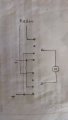
With regard to your schematic, I’d draw junctions closer to one device or the next. Drawn out, with junctions made in the middle of the traces, makes it difficult to discern their function. The next paragraphs explain how this works.
I’d break the schematic into functional segments. You pretty much have done this. This problem breaks down into power, master control, individual motor control and outputs or the motors.
I’d also use bus lines for common connections. Right to left for power and common signals (wires common to various functional segments of the circuit) and vertical for connections common to components in a functional segment.
As far as your consideration of other attributes, it depends on the circuit. Typically, I double check that the requirements of each functional segment are met. Such as signal voltage/current/impedance matching. Then, consider each individual component and ensure that they are selected appropriate to their use. E.g., don’t use a 1/8W resistor in a circuit where it is presented with 1/2W.
This problem has none of these considerations. You are using all passive components (switches). Your only remaining consideration is if the power supply (batteries) can supply enough current for all four motors at the same time. And if the power can supply that current long enough for your purposes.
All of these concerns require knowledge of the information in datasheets. Again, this problem just requires having the power supply datasheet and the motors datasheet.
Okay, I´ll make the junctions closer to the devices and more spaced out. Not completely sure about how the bus lines work. Could you send a quick sketch as I can´t seem to find anything in google?
Also, for the part about the current of the motors, does that mean that if each motor draws 1A at 24V, I´m going to need a battery with a max capacity of at least 4A to power all of the 4 motors at the same time?
 Facebook
 Google
 GitHub
 Linkedin