Facebook
 Google
 GitHub
 Linkedin
djsfantasi
- Joined Apr 11, 2010
- 9,237
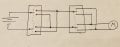
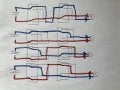
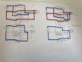
Good catch! If one switch was direct and the other was reverse, you’d have a direct short. Can you see how? Try using different colors and trace the power connections.Hmm, I got the following circuit, but not sure if it would work if one switch is set direct and the other on reverse
Thanks for the motivation btw!! And for your help")
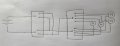
I’ll make a suggestion. What if you put the switches in series? One after another? Try to draw a circuit for that.
P.S. it will have a flaw, see if you can figure out what the flaw is. But draw the circuit anyway. It’ll help you understand the next step.