4-bit binary

Thread Starter

chrisvicor

Joined Sep 11, 2024
9
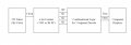
pls help! so im making this project where I make a 4 bit binary counter with modified seven segment. i barely get the gist of it and I couldn't get my schematic right. basically the procedure needs a 7493 synchronus counter that counts from 0000-1111 (00-15 on seven segment) driven by a 555 timer that pulses 1hz. but im not allowed to use a decoder (7447), in which will resort to combinational logic gates(?). i need help, this is not really my strong suit and i wanna pass my course. im an undergrad and in this course i just mostly do self study since my professor is no help. i've attempted this for 3 terms and i just couldn't figure it out.
 

MrChips

Joined Oct 2, 2009
34,628
You need to draw what you want displayed on the 7-segment display for each of the 16 binary values.

Next, for each segment, draw the Karnaugh map showing all 16 states.
 

dl324

Joined Mar 30, 2015
18,220
Welcome to AAC!
im not allowed to use a decoder (7447)
That's fine because 7447 won't do what you want.
i just mostly do self study since my professor is no help. i've attempted this for 3 terms and i just couldn't figure it out.
Do you have classmates you can talk to? Surely someone understands the material.

Show us your work so we can see where you're getting stuck.

I did this decoder design for fun. It took me about 5 dozen gates.
 

Ian0

Joined Aug 7, 2020
13,097
A good place to start would be the 7447 datasheet.
The 7447 is so old that manufacturers still put all the logic diagrams in the datasheet.
Then you need to add ABCDEF.
 

MrChips

Joined Oct 2, 2009
34,628
It is possible that you could design the decoder with just resistors and diodes, called RDL (resistor-diode logic).
 

Thread Starter

chrisvicor

Joined Sep 11, 2024
9
"Do you have classmates you can talk to? Surely someone understands the material."
Not really, i've talked with a couple of people I know in the same course as me and they didn't have any clue either

"Show us your work so we can see where you're getting stuck.
I've done the 555 timer setup to 1hz, as well as the attached picture. It's not much, haven't really figured how to connect the pins of the combinational gates right. I just purely based on what I learn in the internet but it's still puzzling me.
 

Attachments

Last edited:

Thread Starter

chrisvicor

Joined Sep 11, 2024
9
Did you look at the 7447 data sheet?
Yeah I did that as well as doing a schematic for it but when I attempted to test it on a breadboard it won't work. To be frank, I didn't have any initial understanding with it as I am new with this field and it's just confusing :(
 

Thread Starter

chrisvicor

Joined Sep 11, 2024
9
It you are self taught, then who is giving the limitation on using a 7447?
Just to provide context, I study under a fully online program. It is modular, meaning no meetings with facilitators or anything. They ONLY give us reading materials and school tasks. This was the FINAL task I had to do which I still couldn't figure out. The facilitator was the one who gave the restriction.
 

Ian0

Joined Aug 7, 2020
13,097
The way to tackle a big problem is to break it down into a series of smaller problems, and this easily breaks down into 7 circuits, one for each segment.
So you have 7 instances of a combination logic problem with four inputs and one output. Doesn't that sound rather easier?
And you have information from a real expert (whoever designed the TTL series at Texas Instruments back in 1964) who has solved most of the problem and given you a circuit diagram.
 

boostbuck

Joined Oct 5, 2017
1,034
Ok, rather than just saying you don't understand, you should suggest solutions to this group and ask for constructive criticism.

It does seem that a combinational solution should be pretty straightforward, since you have the 7447 datasheet as a guide. Alternatively, a ROM for decoding would be simpler perhaps (if you can use a ROM).

What is stopping your progress? You say you have done a schematic but can't breadboard it successfully. If you post the schematic here we can see what you propose. How does the breadboarded circuit fail? Have you tried incrementally building the logic on the breadboard, testing as you go, to validate each subsection?
 

WBahn

Joined Mar 31, 2012
32,704
Just to provide context, I study under a fully online program. It is modular, meaning no meetings with facilitators or anything. They ONLY give us reading materials and school tasks. This was the FINAL task I had to do which I still couldn't figure out. The facilitator was the one who gave the restriction.
Someone asked before what course this is for? What is the title of it? That gives us an idea of what you are expected to learn and some hints as to what you are probably expected to know coming into it.

If this is any kind of a digital electronics course and this is your final task in the course, then either you should consider a different major, or consider going to a different school -- especially if this is your third attempt at the same course.

Since you need to display the value as two decimal digits, why are you using a binary counter (7493) instead of a decade counter (7490)?

Instead of trying to drive two 7-seg displays from a 4-bit binary value, how about converting the binary value to two BCD values?

If you have some 7447 chips, you could then (as an intermediate step), use those between your BCD values to drive your displays to verify/debug/correct your circuit up to that point. Then it's just a matter of making two implementations of the logic in the 7447 datasheet. If you give it some thought, you can make significant simplifications on the tens display (as in, you can go direct from your binary output to your 7-seg display (assuming it's common cathode) using a single 7402 without even using all the gates in that package. Even the logic in the 7447 datasheet can be significantly simplified given that you don't need all of its functionality. It's still quite a bit of wiring, so you should definitely implement and test it one segment at a time.
 
Top