4 Bit Adder build - chip outputs make no sense

Thread Starter

Miguel0077

Joined Dec 8, 2018
2
Hello
Just joined the forum and I'm a novice so, apologies if my question is a bit daft.
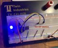
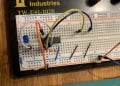
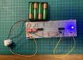
Trying to make a 4 bit adder, but as soon as I tested a simple chip with AND gates (tested 3 in case 1st was faulty) it doesn't seem to make sense.
Dip switches: A : ON B :OFF (A and B should be OFF) and LED is ON.
LED is only off if both A+B are off
(photo for reference in case I messed up connecting anything)
Many thanks in advance

Miguel

CHIP CD4081BE

PS - on that first XOR gates chip I don't even need to connect A or B if A+B output goes to LED, it lights up. (very frustrating)
 

Attachments

Thread Starter

Miguel0077

Joined Dec 8, 2018
2
Hi guys
Thanks for the replies.
I get the schematics and logic. What's driving me crazy is that, at the very basics -> just 1 gate on a chip doesn't make sense.
I've now even changed breadboard
Even took off dip switch. The LED lights up every now and then. I think my frustration gives off wireless electricity.
Could it be way I'm powering this up? (4x 1.5v)
 

Attachments

MrChips

Joined Oct 2, 2009
30,714
This is a common mistake made by newcomers to digital circuits.

What this the logic input to a gate when nothing is connected?
It is a common mistake to assume that the logic input is 0.

It depends on the technology used to design the chip as well as the family of the chip.
Do not assume any logic input, 0 or 1.

In order to test the gate, connect the input to logic 0 (GND) or logic 1 (Vcc).

There are other important rules that you will have to learn, such as what to do with unused inputs.
You can use pull-up and pull-down resistors but you need to tell us the exact part number of the chip.
 

dl324

Joined Mar 30, 2015
16,846
Cropped photo:
upload_2018-12-8_9-45-34.png
Orange wire in power rails is 6V, the yellow wire that's clipped connects. Blacked out the LED so it doesn't distract.

It seems that your problem is that you don't know how to use the integrated circuits. It looks to me like the gate inputs float when you open switches. Have they taught you that you shouldn't leave inputs floating?
 

MrChips

Joined Oct 2, 2009
30,714
If you are using CMOS gates, any value resistor from 1kΩ to 100kΩ will do as a pull-up (logic 1) or pull-down (logic 0).

Remember that you need to connect ALL INPUTs to a logic 0 or logic 1 or suffer the consequences.
 

WBahn

Joined Mar 31, 2012
29,979
And it's important to note that ALL INPUTs means exactly that and includes all inputs of any gates on the chip that you don't happen to be using. Leave unused outputs unconnected.
 
Top