Facebook
 Google
 GitHub
 Linkedin
Hi all,
I have recently been given an air compressor that was in need of some repairs. I was hoping to be able to get this all done on my own, but I am totally stuck when it come to re-wiring the motor and capacitors.
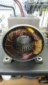
The motor itself is a single phase, 240v, 3Hp unit. Its marked MEC 90 L, but I believe this is more of a description of the physical dimensions than the electrical side of things from what I have looked at on the net.
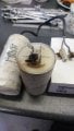
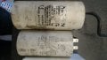
I have two old, and clearly blown capacitors and two new replacements. One is 70uF the other is 55uF. So I have assumed that this is a Capacitor start, capacitor run motor, and that the 70uF is the start and the 55uF is the run. I have searched all over the place for an internal wiring diagram and just cannot find one, and for the life of me I cannot figure out how to connect it up properly.
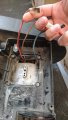
Coming from the motor are 3 wires, they are not marked in any way. So I will call them A, B and C for now. The resistances across them are as follows, approximately, I was using an analogue meter and cannot remember the exact numbers now:
A - C = 0.5 Ohm
B - C = 1.5 Ohm
A - B = 2 Ohm
So to me this suggests that A & B are the start and run windings, with C being common. I loosely understand the principals of wiring the motor, but I keep finding conflicting information on the internet as how it should be wired. Some places say both capacitors should be in parallel across both coils, with the Start cap being switched out by a centrifugal switch when the motor is up to speed, others seem to suggest that the run cap be in parallel with the start cap in series. Either way, I can't get my head around how to do this with just the 3 wires. In my head I need four.
So does anyone have any ideas or tips on what I could look at next? I would really love to get this going.
Thanks in advance
Chris
I have recently been given an air compressor that was in need of some repairs. I was hoping to be able to get this all done on my own, but I am totally stuck when it come to re-wiring the motor and capacitors.
The motor itself is a single phase, 240v, 3Hp unit. Its marked MEC 90 L, but I believe this is more of a description of the physical dimensions than the electrical side of things from what I have looked at on the net.
I have two old, and clearly blown capacitors and two new replacements. One is 70uF the other is 55uF. So I have assumed that this is a Capacitor start, capacitor run motor, and that the 70uF is the start and the 55uF is the run. I have searched all over the place for an internal wiring diagram and just cannot find one, and for the life of me I cannot figure out how to connect it up properly.
Coming from the motor are 3 wires, they are not marked in any way. So I will call them A, B and C for now. The resistances across them are as follows, approximately, I was using an analogue meter and cannot remember the exact numbers now:
A - C = 0.5 Ohm
B - C = 1.5 Ohm
A - B = 2 Ohm
So to me this suggests that A & B are the start and run windings, with C being common. I loosely understand the principals of wiring the motor, but I keep finding conflicting information on the internet as how it should be wired. Some places say both capacitors should be in parallel across both coils, with the Start cap being switched out by a centrifugal switch when the motor is up to speed, others seem to suggest that the run cap be in parallel with the start cap in series. Either way, I can't get my head around how to do this with just the 3 wires. In my head I need four.
So does anyone have any ideas or tips on what I could look at next? I would really love to get this going.
Thanks in advance
Chris