 Facebook
 Google
 GitHub
 Linkedin
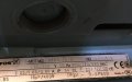
Hello All, this is my first time posting here on this wonderful forum. I have here a grundfos motor that allows wiring the stator poles to select speeds. It is a 3-Speed 900 / 720 / 530 rpm 220V 50Hz with 16uF 400V Capacitor and 0.22KW Size Motor. It is perfect for my application but it is my first experience with anything of this sort therefore seeking some help or suggestions as to what is realistically achievable.
There are two parts to my question. Images are attached below.
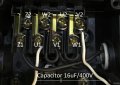
1. I want to add toggle switches(?) to be able to adjust speed (Low-Med-High) - this motor was salvaged from some heating/cooling equipment a while ago as i was told and doesn't come with anything else but the speed control wiring diagram on the box.
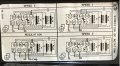
2. The Speed setting diagram on the back of the electrical box is confusing to me, but i can understand that changing between speed 1 and speed 2 only requires the capacitor Wire to be attached to U1-U2 instead of U1-V2
Diagram for speed 1 and speed 2 there seems to be two jumper wires from U2-W1, does this mean i have to physically use two wires to jump the two terminals?
Dotted lines that denote MAIN1 MAIN2 and AUX, i have no idea what they mean.
Lastly, i can tell you the extent of my knowledge. I'm a tinkerer and a hobbyist but all my experience has been with dc related led's, pcb's and led circuits so this is (very) new to me.
Thank you for reading through my question, i hope you can take some time to answer a few things.
Best regards,
Scholl
There are two parts to my question. Images are attached below.
1. I want to add toggle switches(?) to be able to adjust speed (Low-Med-High) - this motor was salvaged from some heating/cooling equipment a while ago as i was told and doesn't come with anything else but the speed control wiring diagram on the box.
2. The Speed setting diagram on the back of the electrical box is confusing to me, but i can understand that changing between speed 1 and speed 2 only requires the capacitor Wire to be attached to U1-U2 instead of U1-V2
Diagram for speed 1 and speed 2 there seems to be two jumper wires from U2-W1, does this mean i have to physically use two wires to jump the two terminals?
Dotted lines that denote MAIN1 MAIN2 and AUX, i have no idea what they mean.
Lastly, i can tell you the extent of my knowledge. I'm a tinkerer and a hobbyist but all my experience has been with dc related led's, pcb's and led circuits so this is (very) new to me.
Thank you for reading through my question, i hope you can take some time to answer a few things.
Best regards,
Scholl
Attachments
-
 176 KB Views: 18
 -
 178.2 KB Views: 15
 -
 110 KB Views: 17


