3 phase inverter bridge

SgtWookie

Joined Jul 17, 2007
22,230
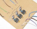
220k should be fine for DT/SD for the moment. Really, you're in a "debug" mode for now, and increasing the dead time will help to ensure that you don't have a "shoot-through" condition. Having that long wire to your uC was begging for trouble; it could pick up noise inductively from other wires.

Sure, an electrolytic would be fine for the 10uF.
The main thing is the smaller 0.1uF cap. It takes care of the higher frequency transients. The 10uF cap takes care of larger transients, like when (eventually) your 3-phase induction motor is being powered by the bridge. Your currently "clean" 24v supply will start having lots of noise on it. The RC network, in conjunction with the Zener in the IC, should result in a pretty clean supply for the IC.

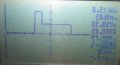
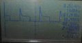
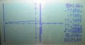
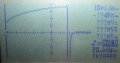
Next time you test-run the bridge, keep using the 1k resistor to the +24v supply to limit max current throught the bridge. Also, put another resistor (basically, 5k to 50k) from the middle of the bridge to ground. I can't yet explain why you were getting that 12v output trace (where the two 24v glitches were) - it may be a result of gate/drain/source capacitance. Adding a resistor to ground from the middle of the bridge should help to clear that up, and still keep your current levels low.
 
Last edited:

Thread Starter

ShaunManners

Joined Feb 16, 2008
72
Ok, here's my updated circuit... all values are as we have discussed.. I haven't yet put in the 5-50k between the centre of the bridge and ground... unfortunately I have run out of time and have to go to work now... I'll see if I cant test it out later tonight when I get home.

Edit:
I turned it on this evening, shortly after the ICs and supply resistors got very hot indeed... not sure why.. I'll have another play with it tomorrow, I just thought I'd give you an update :)

Cheers
Shaun
 

Attachments

Last edited:

Thread Starter

ShaunManners

Joined Feb 16, 2008
72
Ok so I'm an idiot!

I put the 100 and 220 ohm resistors in parallel rather than series... resulting in an equivalent of 68.75 ohms... whoops!
no wonder they were getting hot (enough to melt the plastic end of my o-scope probe!)

They are very resilient ICs though! When it got too hot it shut down... and it still works even now.
I'll hook it up to the MOSFETs (half bridge) now and report back... the full bridge will have to wait till tomorrow unfortunately.

Edit:
Ok, I put the scope between ground and the centre of the bridge and got pretty much the same as before.. although alot cleaner this time... occasionally there were a few blips in the 12v bit, but they were tiny and went slightly lower rather than appraching 24v.

I just had a thought, do you think its my bootstrap caps that aren't a high enough capacity... their voltage drops and thats where the FETs turn half off? or am I just talking rubbish? would the voltage curve down just like the discharge curve of the caps...

Cheers
Shaun
 

Attachments

Last edited:

SgtWookie

Joined Jul 17, 2007
22,230
I put the 100 and 220 ohm resistors in parallel rather than series... resulting in an equivalent of 68.75 ohms... whoops!
no wonder they were getting hot (enough to melt the plastic end of my o-scope probe!)
Oops! :eek:

They are very resilient ICs though! When it got too hot it shut down... and it still works even now.
You just plain got lucky! ;)
I'll hook it up to the MOSFETs (half bridge) now and report back... the full bridge will have to wait till tomorrow unfortunately.
That's OK.

Edit:
Ok, I put the scope between ground and the centre of the bridge and got pretty much the same as before.. although alot cleaner this time... occasionally there were a few blips in the 12v bit, but they were tiny and went slightly lower rather than appraching 24v.

I just had a thought, do you think its my bootstrap caps that aren't a high enough capacity... their voltage drops and thats where the FETs turn half off? or am I just talking rubbish? would the voltage curve down just like the discharge curve of the caps...
One sure way to find out - add more capacitance to them! :)

If you added those 2k pull-down resistors to the gates, that would tend to pull the charge off the bootstrap caps fairly quickly. You might try increasing them to, say, 20k or 50k. The idea was to not roast your MOSFETS in case you powered the thing up with the drivers disconnected. However, such a low value of pull-downs may be problematic when you're running at low frequencies.
 

Thread Starter

ShaunManners

Joined Feb 16, 2008
72
ok... following on from my bootstrap cap idea... I put the scope betweent he centre of the bridge and the gate of the high side.. which resulted in the trace in the attached picture (sorry about the quality)... looks rather familiar! I think the cap is running dry basically... and it is keeping the FET on for almost two tenths of a second... I will eventually be doing much higher frequencies.. so it should hold up fine :D

do you think my reasoning is sound?

Cheers
Shaun
 

Attachments

Thread Starter

ShaunManners

Joined Feb 16, 2008
72
One sure way to find out - add more capacitance to them! :)

If you added those 2k pull-down resistors to the gates, that would tend to pull the charge off the bootstrap caps fairly quickly. You might try increasing them to, say, 20k or 50k. The idea was to not roast your MOSFETS in case you powered the thing up with the drivers disconnected. However, such a low value of pull-downs may be problematic when you're running at low frequencies.
I'd have to order some higher value tantalum caps to try that... I have some 10uF ones... but they are rated at 16v, so not much good :)
I'll deffinately do that though just to find out!

regards the resistors... I'll put some higher values in then... try and make it more idiot proof ;)

Cheers
Shaun
 

SgtWookie

Joined Jul 17, 2007
22,230
ok... following on from my bootstrap cap idea... I put the scope between the centre of the bridge and the gate of the high side..
which resulted in the trace in the attached picture (sorry about the quality)... looks rather familiar! I think the cap is running dry basically... and it is keeping the FET on for almost two tenths of a second... I will eventually be doing much higher frequencies.. so it should hold up fine :D
Well, I can't tell what your volts/div setting is. You should have around 10v on the gate while the MOSFET is ON, and ideally go right to 0v afterwards.

Like I said, if you still have the 2k pull-down resistors on the gates, they are likely too low in resistance for the low frequency at which you're driving the gates. As I already mentioned, I wouldn't remove them entirely - as you have two separate boards, and if you ever forget that you have to have them hooked up together before turning them on again, you'll be serving fried MOSFETs. :eek: ;) Instead, increase them to 10k or 20k.

It may be that increasing the pull-down resistors is enough, and you don't need to increase the boost caps. However, you might need to parallel the boost caps with low-value ceramic or tantalum boost caps; as the larger 0.47uF boost caps may have too much impedance - even though this isn't likely at such low frequencies, it's still worth a try.
 

Thread Starter

ShaunManners

Joined Feb 16, 2008
72
ok, so I have increased the frequency and it worked perfectly... I have put in the other half bridges to complete the full 3 phase bridge...

I attached the alternator... nothing happened... guessed it was the 1k resistor, put the meter across it and it was indeed dropping the full 24 volts (if I remember correctly, the alternator windings are about 3 ohms)...

I was reluctant to remove it because of the chance of blowing up the mosfets again... but went for it anyway... still nothing... while I was pondering one of the mosfets cracked... none of them got hot or even warm...

I'm pleased to have gotten the bridge to work... but... just puzzled and not sure what to do next...

Cheers
Shaun
 

Attachments

SgtWookie

Joined Jul 17, 2007
22,230
Shaun,
It's really too bad that you tried hooking up the alternator so quickly.

You won't be able to connect it when the 3-phase bridge is running at a low speed (you had it at roughly 9Hz), because the coils in the alternator will quickly saturate, and appear as nearly a dead short. We just weren't quite that far along yet.

What is the alternator that you're working with? What did it come out of?

I think that what your best course of action to take at this moment, is to set the bridge and control board aside, and figure out what that time-to-saturation is.

And here's a link to a page that will help a great deal in figuring that out:
http://www.dos4ever.com/flyback/flyback.html
Ronald's "Flyback Converters for Dummies" page!
Really, it's not for dummies - Ronald just has a great sense of humor ;)

If you want to skip-read, scan down to "An inductor test bench". His schematic for a test bench is really mostly useful for smaller inductors, but it could be adapted for larger ones, such as your alternator. Look below that, and you'll see what happens on a scope when an inductor saturates; the voltage across it drops like a rock, meaning that the current through it is simultaneously skyrocketing.

Apparently, you have no current feedback loop in your bridge. If you did, it either did not function or it is not correctly set up. If you don't, you need one.

After you're done digesting a few things on Ronald's page, why not update your schematic and post what your current configuration is?
 
Last edited:

Thread Starter

ShaunManners

Joined Feb 16, 2008
72
It's really too bad that you tried hooking up the alternator so quickly.

You won't be able to connect it when the 3-phase bridge is running at a low speed (you had it at roughly 9Hz), because the coils in the alternator will quickly saturate, and appear as nearly a dead short. We just weren't quite that far along yet.
ah ok... sorry...

What is the alternator that you're working with? What did it come out of?
The one I'm testing with is from an old 12v generator... I don't really know much more than that..

I think that what your best course of action to take at this moment, is to set the bridge and control board aside, and figure out what that time-to-saturation is.

And here's a link to a page that will help a great deal in figuring that out:
http://www.dos4ever.com/flyback/flyback.html
Ronald's "Flyback Converters for Dummies" page!
Really, it's not for dummies - Ronald just has a great sense of humor ;)
Ok, I've read through that section a few times... I'll order the components today... but how exactly would I need to change it for my alternator?

one other question... it says "When the transistor is opened, the inductor can dump its energy in diode D4" but I can't see D4 on the schematic... also, where does the logic side and those caps/resistors get their power from? there appears to be no supply...

he certainly does have a sense of humour saying its for dummies ;)

Ok, I'll draw up a new schematic of my current setup...

What sort of current sensing resistor should I use? I think my dad has a shunt he's not using, but I don't know what value it is... but if you could suggest a value then I might be able to order one or check out what value this shunt is.

Cheers
Shaun
 

ronald

Joined May 15, 2008
1
Hi Shaun,

Thank you for appreciating my sense of humor.

Diode D4 should be D3, I will correct that.

The power supply for the inverters is the same 12V as used for the
inverter

regards

Ronald
 

Thread Starter

ShaunManners

Joined Feb 16, 2008
72
Hi Shaun,

Thank you for appreciating my sense of humor.

Diode D4 should be D3, I will correct that.

The power supply for the inverters is the same 12V as used for the
inverter

regards

Ronald
Hi Ronald,

A sense of humor is always good! ;) I have a feeling I am going to be putting the dummy bit to the test ;)

Thanks for clarifying my two questions... just out of curiosity, what FET were you using?

Cheers
Shaun
 

Thread Starter

ShaunManners

Joined Feb 16, 2008
72
Hi There SgtWookie,

Well, I have built that circuit, the only difference is I used that spare shunt which has a resistance of 0.2 - 0.3 ohms (meter kept flicking between the two) and I used a 12v supply.

Other than that, the circuit should be identical to Rons schematic... I did realise afterwards that I had the ground and the probe the wrong way round, but I presume this would just invert the signal?

now the thing is... I'm not really sure what I'm looking at! the one with the nice curve is the inductor... the other one is testing the alternator...

I'll get that updated schematic done tomorrow.

Cheers
Shaun
 

Attachments

SgtWookie

Joined Jul 17, 2007
22,230
The one with the nice curve (inductor) is starting to build up towards saturation.
The alternator is nearly flat-line, because it's such a large inductor it hasn't approached it yet.
 

Thread Starter

ShaunManners

Joined Feb 16, 2008
72
The one with the nice curve (inductor) is starting to build up towards saturation.
The alternator is nearly flat-line, because it's such a large inductor it hasn't approached it yet.
ok, sorry it has taken me so long to reply... I have been having a hectic week...

I increased the resistor in the test circuit to 47k (the one in series with the 50k variable resistor) in order to (I believe) increase the on time of the FET... the attached is what I got when testing the alternator... looking better, do I need to increase the time even more? or is that saturated there? if it is then I am a little bit concerned at the frequency that will be required.

oh and I haven't forgotten about updating that schematic... will do so at the next chance I get.

Cheers
Shaun
 

Attachments

SgtWookie

Joined Jul 17, 2007
22,230
Why no values for R and C anywhere?

Oh, and you have yet to mention how much current you're putting through the rotor, or how you're controlling that current.

Without rotor current to generate a magnetic field for the field windings to interact with, the rotor will not turn.
 

Thread Starter

ShaunManners

Joined Feb 16, 2008
72
All the values are as we have previously discussed... but I'll put a list together tomorrow just to confirm...

As for the rotor.. well I tried connecting both ends together to make it an inductance motor... and I have also tried connecting it to a 12v battery... no special current control...
 

SgtWookie

Joined Jul 17, 2007
22,230
All the values are as we have previously discussed... but I'll put a list together tomorrow just to confirm...
Well, a schematic is rather like a recipie. It's not quite enough to say that flour, sugar and butter go into baking cookies - unless you don't care if you wind up with a sticky burnt mess in the oven! :eek:

As for the rotor.. well I tried connecting both ends together to make it an inductance motor... and I have also tried connecting it to a 12v battery... no special current control...
Well, you're going to need SOME kind of current flow through it - otherwise, it'll just sit there asking you to turn the heat up. :confused:

Before trying it again, how about getting some high-wattage low-value resistors to limit the current to something safe. Let's suggest that 3 Ohms in each leg and in series with the rotor will limit your current to I=E/R, or 8 Amperes. Your MOSFETS and the rotor windings should be able to handle that; although your heat sinks on your MOSFETS are terribly minimal.

So, the resistors will need to be capable of handling around 100 Watts each. Rather large, eh? You might make do with some lightbulbs from the auto salvage yard. Four headlamps per phase, two in series in parallel with another two in series.
 

Thread Starter

ShaunManners

Joined Feb 16, 2008
72
Well, a schematic is rather like a recipie. It's not quite enough to say that flour, sugar and butter go into baking cookies - unless you don't care if you wind up with a sticky burnt mess in the oven! :eek:
Nice analagy ;) I have just managed to sit down and update the circuit schematic, see attached... hopefully this one will prove to be more useful!

Well, you're going to need SOME kind of current flow through it - otherwise, it'll just sit there asking you to turn the heat up. :confused:

Before trying it again, how about getting some high-wattage low-value resistors to limit the current to something safe. Let's suggest that 3 Ohms in each leg and in series with the rotor will limit your current to I=E/R, or 8 Amperes. Your MOSFETS and the rotor windings should be able to handle that; although your heat sinks on your MOSFETS are terribly minimal.

So, the resistors will need to be capable of handling around 100 Watts each. Rather large, eh? You might make do with some lightbulbs from the auto salvage yard. Four headlamps per phase, two in series in parallel with another two in series.
Ok, so fixed resistors in series with each leg will be current limiting... could you explain why it needs this because between two legs (its connected in star formation) is about 3ohms... sorry if this is obvious.

The reason the heatsinks are minimal is mainly for a couple of reasons, 1: I don't have a lot of space under the bonnet of my train, so needed to keep the bridge as small as possible, and 2: they should only be used for short periods of time when starting the engine

Cool idea about using headlamp bulbs! I'll either call in a local scrap yard next week, or I might just order something like this if you think it'd be ok... I guess scrap yard would be cheaper ;)

Cheers
Shaun
 

Attachments

Top