 Facebook
 Google
 GitHub
 Linkedin
i would appreciate if anybody could help me with a circuit design for an Equalizer. i should realize the board for a connection with STM32F411 Discovery (it would be a second part of task).
It is an example for a study. Recently i received this project to realize, original text is in German but there are details:
3 Channel Equalizer:
Bandpass for frequencies 100Hz, 1kHz, 10 kHz
those frequencies should be gained trough potentiometer from +12dB to -12dB
Band-passes should be min 4th order
as an input source should be used BNC-socket
output signal to be transmitted to an existing AD channel
simulation in Multisim or Spice
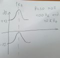
i added a picture of an expected gain graph (potentiometer should limit gain between +12dB and -12dB)
Thanks for help
i guess that the way of circuit design is not as much complicated for someone who already has experience with this tasks
It is an example for a study. Recently i received this project to realize, original text is in German but there are details:
3 Channel Equalizer:
Bandpass for frequencies 100Hz, 1kHz, 10 kHz
those frequencies should be gained trough potentiometer from +12dB to -12dB
Band-passes should be min 4th order
as an input source should be used BNC-socket
output signal to be transmitted to an existing AD channel
simulation in Multisim or Spice
i added a picture of an expected gain graph (potentiometer should limit gain between +12dB and -12dB)
Thanks for help
i guess that the way of circuit design is not as much complicated for someone who already has experience with this tasks
Attachments
-
 318.6 KB Views: 9


