 Facebook
 Google
 GitHub
 Linkedin
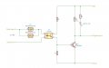
Correctr=5v-(0.2v+3.6v)/20ma
r=60ohms
so I need 2.0mA through the base of the transistor
OR 200ua/30% = 666uA though the TLP290 input
Rin290 = 3 - (Vledin290) / 666 uA = (3 - 1.4) / 666 uA
=`2.4K
No. P = E^2 / R = (30 - 1.4)^2/2400 = .34Wwattage for Rin290 = (30max-1.4)x666uA
=~20mW
Regards, Dana.


")


