3-30V (Sinking/Sourcing) to Arduino Input

Thread Starter

jonfarrugia

Joined Feb 19, 2010
71
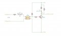
I've been working on a circuit that would take a field digital input ranging from 3-30 to feed the input of an arduino. I'd also like an LED to go on when the field voltage is above 3 volts without taking up and arduino output.
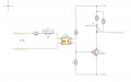
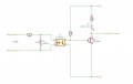
The field input can either be sinking or sourcing so I needed to use a bi-directional op-amp to make this work. Here is the circuit so far. I'm definitely no expert so I could use a little help to design this one.


Attachments

Ya’akov

Joined Jan 27, 2019
9,069
Multiple threads on the same topic are generally frowned upon. The post could have been appended to the existing thread and it would cause less confusion than this way will.

It's not a big deal but I suspect some people are going to be put off by the double posting. Just a heads up for future reference.
 

Sensacell

Joined Jun 19, 2012
3,432
I see where you are trying to go with this, but the posted design has a number of problems.

3-30 V is a large input range to contend with.
The way it is now, the LED current will vary from 1.8 to 28.8 mA. You will need a 1 Watt resistor to contend with the power dissipated in the input resistor.

The BAT54C does nothing? what is it there for?

The way you have the white LED and a transistor connected the output voltage will not go full 0-5 V.
The white LED will subtract about 3.2 V, it will only make it to 1.8 V OUT = HIGH (fail)
When the output goes LOW, it can never get below Vbe + Vce sat of the phototransistor- maybe around 0.9V (fail)

Reconfigure it for an NPN transistor with a grounded emitter, so the transistor can pull the output to near 0V.
Put a pull-up resistor in parallel with the White LED and limiting resistor, so the output will go up to +5V.

Consider the possible 10 uA leakage current from the optocoupler.
Consider the maximum base current - worst case - could be 4X the LED current!!
 

danadak

Joined Mar 10, 2018
4,057
To detect 3V use another TL290 and a couple of 2.4V zeners.

Here is a sim, the two diode to right simulating TL290 input diodes.

upload_2019-5-6_7-54-37.png

Regards, Dana.
 

Sensacell

Joined Jun 19, 2012
3,432
@Sensacell thank you for the input! Indeed, I don't care about the speed; I will put a series resistor as a precaution.
The 10 K from pin 4 TLP290 to Vcc, should be pin 4 to ground.
Regards, Dana.
You mean pin 3 goes to the base? right?

I would put a 27 K from base to ground, to prevent leakage current from turning Q1 on.
Put the 1K between +5V and pin 4.

The 2.4V Zener and the LED Vf combine to be about 3.6V it will not turn on until you get a bit over that. You have two of the BZB784 diodes in circuit, this adds another volt to the threshold, use just one. (terminals 2 and 1 only)
 

danadak

Joined Mar 10, 2018
4,057
I stand corrected, with respect to base connections.

The 2.4V Zener and the LED Vf combine to be about 3.6V it will not turn on until you get a bit over that. You have two of the BZB784 diodes in circuit, this adds another volt to the threshold, use just one. (terminals 2 and 1 only)
You need a 2 zeners because the field polariy can be + or -. You can get 1.8 V and 2.0 V zeners
to move the trip point.


Regards, Dana.
 

danadak

Joined Mar 10, 2018
4,057
Take worst case V across each R, P = E^2 / R, volts, ohms.

So lets do the LED R first.Vr = 5V - (Vled + Vsat3904). Vsat3904 ~ .2V
White LED Vled =~ 3.6 V (look at datasheet).

So P = [5 - ( 3.6 + .2)]^2/200 = ~7 mW

That was a nominal calculation. Normally you would use worst case #'s for
everything, max V's, min Rohms.

Regards, Dana.
 

Thread Starter

jonfarrugia

Joined Feb 19, 2010
71
According to my calculations, I would need a 1w resister on the input of the TLP290.

30-(3.3+1.2)^2/1000 = 0.625w

Does this resistor really need to be 1k?
Could I go with a 10k?
 

danadak

Joined Mar 10, 2018
4,057
Your LED has ~ 6 mA thru it. Ruled of thumb to saturate the 2N3904 you
want Ic/10 driven into the base, so Ib = Ic / 10 = 600 uA.

To saturate the TLP290 output we have to take into accout the CTR.

Its nominal 60%, so we need to drive the input with 600 uA / 10 or 60 uA.
But then CTR makes that 60 uA / 60% =~ 100 uA. 60% is a nominal number
from datasheet. You might want to use the 30% number.

The input worst case is 3V. So Rin290 = 3 - (Vledin290) / 100 uA = (3 - 1.4) / 100 uA
=~ 16K.

You should look at graphs for T effects, probably safe with 10K.

Regards, Dana.

PS : Check my math.
 

Thread Starter

jonfarrugia

Joined Feb 19, 2010
71
How did you get 6ma through the LED? I'm looking to get closer to 20ma through the white LED. 6ma doesn't seem like enough.
 

danadak

Joined Mar 10, 2018
4,057
Iled = [5V - (Vcesat3904 + Vled) / 200 = [5V - (.2V + 3.6V)]/200
=~ 6 mA.

Rled = [5V - (Vcesat3904 + Vled)] / Iled.


Regards. Dana.
 

Thread Starter

jonfarrugia

Joined Feb 19, 2010
71
If I want to increase the current through the white LED to about 20 ma I would need a resister of ~60 ohms

r=5v-(0.2v+3.6v)/20ma
r=60ohms

so I need 2.0mA through the base of the transistor
OR 200ua/30% = 666uA though the TLP290 input

Rin290 = 3 - (Vledin290) / 666 uA = (3 - 1.4) / 666 uA
=`2.4K

wattage for Rin290 = (30max-1.4)x666uA
=~20mW

Does this look correct?
 

Sensacell

Joined Jun 19, 2012
3,432
No,

The current transfer ratio from the data sheets is 50% (minimum) which is a loss, not a gain.

If you want 2 ma base current, you need 4 ma through the TLP290 LED.

Now extrapolate this to your worst-case HIGH input voltage and you will see where the problems is.
 
Top