Facebook
 Google
 GitHub
 Linkedin

Hello Ron_H,
Thanks for replying... I appreciate your help.
>Your schematic has a +5V supply. Is that the only one you have available?
No, there is another separate power supply powering the DAC and the MCU which is 3.3 VDC. These two power supplies don't interfere with each other. The 5VDC is for the IR circuit/Mosfet and the 3.3VDC is strictly used for powering the MCU.
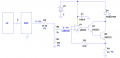
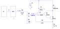
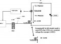
You may look at the new attachment below. Here's what's happening, The MCU supplies 8 bit data to the DAC. It supplies it starting from 0 to 256. Therefore the DAC counts from 0 to 256 and supplies 0 to 5.0VDC to the gate of the mosfet.
When an object is introduced in the infra red's field of vision, lets say for the sake of this example... 8". The output of the MCU is constantly counting from 0 to 256. At binary 0, the DAC obviously outputs 0VDC at VGS. And at this instance there is obviously not current through the mosfet and therefore there isn't enough IR light to bounce off the object and back to the reciever. Therefore at this time the MCU does not see any signal form the TSOP.
As the MCU increments its output to 1, well, still, there is not current through the mosfet and therefore there isn't enough IR light to bounce off the object. The MCU needs to increment its output to approximately 100 where the mosfet's gate sees 2.1VDC which very little current starts to run though the IR led. However, even at this point there is not enough IR to bounce back to the TSOP sensor. Therefore, again, at this time the MCU does not see any signal form the TSOP.
From this point on, every increment the MCU output makes will increase the VGS hence increasing the current through the mosfet. It will come to a point where the MCU count may be at 150 which would provide a high enough VGS (approx 2.5VDC) to the gate of the mosfet. This will cause the mosfet to conduct enough current allowing the IR led to radiate enough IR light to bounce off the object and provide the signal to the TSOP reciever thus warning the MCU that a detection is made.
At this very instance, the mcu logs down the MCU's output count (150) that the DAC received. At this point here is my error:
I have a polynomial formula that takes that 150 and converts it to inches. The formula has been modeled from tests done by placing the object at various inches and logging down the respective amounts of counts to the DAC. This obviously works fine with the mosfet used during the modeling of the formula. But as soon as I change the mosfet, it is obvious that my formula won't work anymore due to the subtle differences from one mosfet part to another.
My IR led draws approximately 0 to 100ma starting from a VGS of 2.0 to 5.0VDC respectfully.
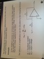
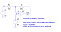
I just thought about something, that might just work. I could read into the MCU the current through my IR led. Which means I would need a current to voltage converter. I can then perhaps re-model my formula in accordance to the distance vs IR led current relation. Then I would know that at a certain current, I must be at a certain distance.
What do you think?
Thanks for your help.
r
Thanks for replying... I appreciate your help.
>Your schematic has a +5V supply. Is that the only one you have available?
No, there is another separate power supply powering the DAC and the MCU which is 3.3 VDC. These two power supplies don't interfere with each other. The 5VDC is for the IR circuit/Mosfet and the 3.3VDC is strictly used for powering the MCU.
You may look at the new attachment below. Here's what's happening, The MCU supplies 8 bit data to the DAC. It supplies it starting from 0 to 256. Therefore the DAC counts from 0 to 256 and supplies 0 to 5.0VDC to the gate of the mosfet.
When an object is introduced in the infra red's field of vision, lets say for the sake of this example... 8". The output of the MCU is constantly counting from 0 to 256. At binary 0, the DAC obviously outputs 0VDC at VGS. And at this instance there is obviously not current through the mosfet and therefore there isn't enough IR light to bounce off the object and back to the reciever. Therefore at this time the MCU does not see any signal form the TSOP.
As the MCU increments its output to 1, well, still, there is not current through the mosfet and therefore there isn't enough IR light to bounce off the object. The MCU needs to increment its output to approximately 100 where the mosfet's gate sees 2.1VDC which very little current starts to run though the IR led. However, even at this point there is not enough IR to bounce back to the TSOP sensor. Therefore, again, at this time the MCU does not see any signal form the TSOP.
From this point on, every increment the MCU output makes will increase the VGS hence increasing the current through the mosfet. It will come to a point where the MCU count may be at 150 which would provide a high enough VGS (approx 2.5VDC) to the gate of the mosfet. This will cause the mosfet to conduct enough current allowing the IR led to radiate enough IR light to bounce off the object and provide the signal to the TSOP reciever thus warning the MCU that a detection is made.
At this very instance, the mcu logs down the MCU's output count (150) that the DAC received. At this point here is my error:
I have a polynomial formula that takes that 150 and converts it to inches. The formula has been modeled from tests done by placing the object at various inches and logging down the respective amounts of counts to the DAC. This obviously works fine with the mosfet used during the modeling of the formula. But as soon as I change the mosfet, it is obvious that my formula won't work anymore due to the subtle differences from one mosfet part to another.
My IR led draws approximately 0 to 100ma starting from a VGS of 2.0 to 5.0VDC respectfully.
I just thought about something, that might just work. I could read into the MCU the current through my IR led. Which means I would need a current to voltage converter. I can then perhaps re-model my formula in accordance to the distance vs IR led current relation. Then I would know that at a certain current, I must be at a certain distance.
What do you think?
Thanks for your help.
r
Attachments
-
 64.2 KB Views: 20
Last edited: