 Facebook
 Google
 GitHub
 Linkedin
Hello everybody!
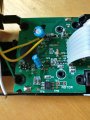
This is my first post in this comunity and I hope to find out how to repair this old train (Image 1) I used to have when I was a kid. Firstly I want to thank you, who takes his time to help me. Let me explain you what's going on.
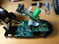
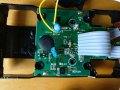
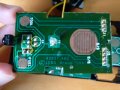
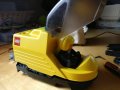
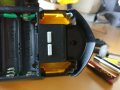
I have (as previously mentioned) a Lego train, bought more-or-less in 2005. The train has a button on it's top (Green cilinder in Image 2&3, board seen in Image 6), which turns the device on and starts off the motor (and some fancy sounds). It has two more buttons, which give each a different sound. There are two more buttons under the train (Image 8), which are used to perform some direction changes during the course of the train, or eventually to stop it*. The system can be turned off with the same button used to turned it on. The thing is, that all the sound and power system is working, but I can't manage to make the motor-system work; at least not as it used to (Clearly seen in the videos, motor should start once the power button's pressed).
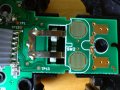
I dismanteled the train, and tried connecting the motor with a low V battery, to see if this was the error. However, it worked perfectly and I'm thinking the error must be somewhere between the microcontroller and the motor. I am a Computer engineering student, so I really don't have the knowledge of an Electric/Electronic engineer; but I believe that could be where the problem is. I attach some pictures and videos to help understand whoever wants to help me the whereabouts of the problem.
Video 1
Video 2
Thank you for reading this and sorry for my broken english, I hope you can help me!")
*This is done once the train's started, some plastic sheets could be placed wherever in the railroad, and the train would do different things such as direction change or stop depending on how long one of this buttons where pressed.
**Two disconected cables can be seen in the pictures, these are the cables that conected the motor with the board, I cut them off to check if the motor was working or not.
This is my first post in this comunity and I hope to find out how to repair this old train (Image 1) I used to have when I was a kid. Firstly I want to thank you, who takes his time to help me. Let me explain you what's going on.
I have (as previously mentioned) a Lego train, bought more-or-less in 2005. The train has a button on it's top (Green cilinder in Image 2&3, board seen in Image 6), which turns the device on and starts off the motor (and some fancy sounds). It has two more buttons, which give each a different sound. There are two more buttons under the train (Image 8), which are used to perform some direction changes during the course of the train, or eventually to stop it*. The system can be turned off with the same button used to turned it on. The thing is, that all the sound and power system is working, but I can't manage to make the motor-system work; at least not as it used to (Clearly seen in the videos, motor should start once the power button's pressed).
I dismanteled the train, and tried connecting the motor with a low V battery, to see if this was the error. However, it worked perfectly and I'm thinking the error must be somewhere between the microcontroller and the motor. I am a Computer engineering student, so I really don't have the knowledge of an Electric/Electronic engineer; but I believe that could be where the problem is. I attach some pictures and videos to help understand whoever wants to help me the whereabouts of the problem.
Video 1
Video 2
Thank you for reading this and sorry for my broken english, I hope you can help me!
*This is done once the train's started, some plastic sheets could be placed wherever in the railroad, and the train would do different things such as direction change or stop depending on how long one of this buttons where pressed.
**Two disconected cables can be seen in the pictures, these are the cables that conected the motor with the board, I cut them off to check if the motor was working or not.
Attachments
-
 192.6 KB Views: 8
 -
 179.3 KB Views: 8
 -
 123.4 KB Views: 8
 -
 175 KB Views: 8
 -
 152.5 KB Views: 8
 -
 152.8 KB Views: 8
 -
 119.5 KB Views: 8
 -
 139.4 KB Views: 8


