2 dc motors in astable mode not working

Thread Starter

sanguine

Joined Apr 16, 2015
16
Hi, am new to this forum and need suggestions for the following issue-

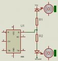
Am using NE555P in astable mode. cap is 1uf. resistor between 6&7 is 570kohm and between 7&8 is 1kohm.

LED is blinking fine. But i want to run 2 motors. Now forget 2 motors,even one is not working. My battery is 9volt.

If am increasing the input volt by giving arnd 15volt, motor is running continuously and its not stopping at intervals.

The Dc motor am using is one i purchased from a local electronics shop and is without specifications.

When am checking the voltage and current across Dc motor by connecting it directly to battery(when its running),
voltage shown is 3.2 volt and current is .6amp. so i guess motor is not getting sufficient current at point 3 of timer IC.

Could someone plz suggest me how to work out this situation. I have copied the schematic from some existing thread as
was not able to make one to post here.

Also i tried using BC548 transistor as switch by giving point 3 output to base, emitter grounded and collector connected to
supply.but still motor is not running.

awaiting suggestions and guidence.
 

Attachments

crutschow

Joined Mar 14, 2008
34,285
When using the transistor, you need a resistor in series with the base.
Where did you connect the motor with the transistor?

A 9V battery is very wimpy and cannot power a motor. Try 6 AA's in series instead.
 

Thread Starter

sanguine

Joined Apr 16, 2015
16
When using the transistor, you need a resistor in series with the base.
Where did you connect the motor with the transistor?

A 9V battery is very wimpy and cannot power a motor. Try 6 AA's in series instead.
Yes when am giving more power like say 15volt by connecting 2 batteries in series,motor is running but not stopping at intervals
the way it shld as per time cycle(which is in my case= 1.1*(570k+1k)*1microfarad = 0.6sec).

Am connecting motor at collector of transistor,emitter grounded and base connected to point 3 with a resistor enough to forward bias base of transistor.

point to be noted- if giving more power,motor is running continuously with transistor as well without transistor, but not stopping
like in astable mode it shld.
 

ScottWang

Joined Aug 23, 2012
7,397
What's your purpose for the value of time intervals is 0.6sec?
0.6 sec is quite a short time intervals, it means that when the motor not stop completely and the next duty cycle is coming again, so maybe you can't see the stop.

And you better to use the bjt or mosfet to driving the motor.
 

Thread Starter

sanguine

Joined Apr 16, 2015
16
What's your purpose for the value of time intervals is 0.6sec?
0.6 sec is quite a short time intervals, it means that when the motor not stop completely and the next duty cycle is coming again, so maybe you can't see the stop.
my purpose is to run one motor at a time,trying to make a toy for my kid, with blinking leds on top, and also want the snake like movement
along with blinking leds.

ok as u suggested will try to increase the time cycle to 3secs and will post my observation here.
 

ScottWang

Joined Aug 23, 2012
7,397
my purpose is to run one motor at a time,trying to make a toy for my kid, with blinking leds on top, and also want the snake like movement
along with blinking leds.

ok as u suggested will try to increase the time cycle to 3secs and will post my observation here.
If the motor with gear then it will be more easy to see it stop, please attach some photos to sharing the toy, and we will get to know it.
 

Thread Starter

sanguine

Joined Apr 16, 2015
16
If the motor with gear then it will be more easy to see it stop, please attach some photos to sharing the toy, and we will get to know it.
hi scott. motor is normal one without gear.

Actually ryt now am just trying to run 2 dc motors in astable mode . so working on bread board only.once things will work, planning to mount them on some plastic body.
ok as we discussed have increased the resistance values 10k between 7 and 8pins and 4.7megaohm between pin 6 and 7. so now duty cycle is coming to = 1.1*(4.7mega+10k)*1microfarad = 5.xx secs.

Still motor not stopping :(. am giving power arnd 15v. also connected motor directly at pin 3 output without transistor.
 

Thread Starter

sanguine

Joined Apr 16, 2015
16
also i took out one dc motor from some existing solar fan toy,which i got from amazon.in. this motor is working fine with my circuit.

this motor is thick coin shaped with armature.

when i measured current across it (when directly connected to battery) it is .5mamp. but am not getting this motor in the shop available in the vicinity.

So somehow want the motor(needing more current arnd .6amp, and is cylindrical shape) to work .
 

ScottWang

Joined Aug 23, 2012
7,397
also i took out one dc motor from some existing solar fan toy,which i got from amazon.in. this motor is working fine with my circuit.

this motor is thick coin shaped with armature.

when i measured current across it (when directly connected to battery) it is .5mamp. but am not getting this motor in the shop available in the vicinity.

So somehow want the motor(needing more current arnd .6amp, and is cylindrical shape) to work .
Can you see the gear in that motor of solar fan toy?
 

djsfantasi

Joined Apr 11, 2010
9,156
If you run gearless motor, shaft will spin fast. When you remove power, shaft will spin for a while due to momentum of rotor. Maybe 0.6 seconds, at which time your next pulse arrives to spin motor.

Have you tried just the motor and batteries, manually pulsing the motor and see what happens? Connect motor to ground and then periodically touch the other end of the battery to the motor terminal. Watch to see if it continues to spin.

Assuming motor runs in one direction (per your schematic), you should have a diode reverse biased across the motor terminals. This will protect the transistor and also cause the motor to stop faster.
 

Thread Starter

sanguine

Joined Apr 16, 2015
16
If you run gearless motor, shaft will spin fast. When you remove power, shaft will spin for a while due to momentum of rotor. Maybe 0.6 seconds, at which time your next pulse arrives to spin motor.

Have you tried just the motor and batteries, manually pulsing the motor and see what happens? Connect motor to ground and then periodically touch the other end of the battery to the motor terminal. Watch to see if it continues to spin.

Assuming motor runs in one direction (per your schematic), you should have a diode reverse biased across the motor terminals. This will protect the transistor and also cause the motor to stop faster.
Yeah I tried running motor just with battery, it is stopping pretty fast. Now my time cycle is 5 sec as am using 10k and 4.7 megaohm resistors,still its not stopping :(
 

Alec_t

Joined Sep 17, 2013
14,280
If at any stage you didn't have a reverse-biased diode across the motor, or the correct value base resistor, you may have fried the transistor. If it has failed short-circuit, that would account for the motor not stopping.
 

Thread Starter

sanguine

Joined Apr 16, 2015
16
If at any stage you didn't have a reverse-biased diode across the motor, or the correct value base resistor, you may have fried the transistor. If it has failed short-circuit, that would account for the motor not stopping.
Alec I guess till now nothing like that happened. Coz LEDs r working fine.IMG_20150608_161231.jpg IMG_20150608_161214.jpg

First image is the motor which is not working. Second image motor is working fine. But I want first image motor to work
 

Ajay More

Joined Jun 8, 2015
3
U can try making ON time(i.e LED oN time/Motor on time) =3sec and OFF time(LED OFF/MOtor OFF time) =6 sec ... duty cycle 33%..

if cost is not the issue, For better result PWM waveform/pulses can given be given to small stepper moto through proper motor driver unit
 

Thread Starter

sanguine

Joined Apr 16, 2015
16
U can try making ON time(i.e LED oN time/Motor on time) =3sec and OFF time(LED OFF/MOtor OFF time) =6 sec ... duty cycle 33%..

if cost is not the issue, For better result PWM waveform/pulses can given be given to small stepper moto through proper motor driver unit
Hi ajay have seen circuits for pwm , but is it really required here. I just want on and off, I don't want to control speed ryt.
Am I missing something, plz elaborate
 

Ajay More

Joined Jun 8, 2015
3
On time and OFF tome matter most to see motor on/oFF state. As u care using Inductive load , astable's duty cycle needs to be controlled properly.
make OFF time more to see motor stop through your naked eye.


if budget is not constraint you can choose stepper motor which can easily controlled with microcontroller based driver units...

For your toy purpose, just ON /OFF application.. make sure duty cycle is correct to see Motor on/off...
you can use variable resistor to very o/p freq. As explain earlier by the time your motor comes to stop state your 555 generates ON pulse so again motor goes in running mode.. so eventually you see motor continue in running mode.....
 
Last edited:

Thread Starter

sanguine

Joined Apr 16, 2015
16
Hi all somehow am able to make one motor run on and off using Darlington pair. But now am stuck with making 2 motors run in as table mode. Below is my schematic for one motor. Could someone suggest how can I put other Darlington pair to make both motors run in as table mode.

IMG_20150611_101133-s.jpg
 
Top