Facebook
 Google
 GitHub
 Linkedin
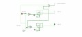
The purpose of the circuit is to lock out switch B when switch A is on, and indicate that a lock out situation exists by "flashing" the LED of switch A when B is pressed.
The switches are, and need to be, momentary types. The relays are, and need to be, non latching types.
I know VERY little about logic chips, so YES, I have no idea if there is a smarter way to do this with different gates or whatever. I played with circuit verse's simulator and the "chips" they offered until I found one (DFF) that would latch and flip the way I wanted.
Trying the simulation for yourself would be best, but I will try to describe it here:
SWITCH A is a switch that can be turned on or off without consequence to the device that this will go into. i.e. it won't hurt nothin.
SWITCH B, however, will do bad things if it is switched when A is on.
Turning A ON will lock B to whichever state it is currently in, ON or OFF.
If one tries to switch B when A is on, the the LED for A will "FLASH" with each press of B to indicate there is a lock situation.
To solve the lock out "ERROR" one just turns A off, switches B to what they want, and then is free to turn A back on.
I hope this makes sense.
There are many ways to solve this, and yes, I have dreamed up mechanical ones with just relays(although not yet with the flashing LED idea.)
This is a bit academic now, as I would love to learn about LOGIC chips. I find this world fascinating.
Attachments
-
312.7 KB Views: 19