19 bit ADC

Thread Starter

kubeek

Joined Sep 20, 2005
5,795
I am trying to replace an old ADC (see http://forum.allaboutcircuits.com/threads/1989-vintage-adc-replacement.85896/ for the old thread)

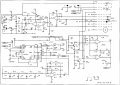
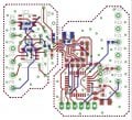
I tried using a 24 bit sigma delta ADC (LTC2440) along with OP1177 opamps and atmega for the interface, but the noise was still high, something like +/- 10 counts on a display with 400000 range IIRC. The measured value itself is sensed at a resistor - the circuit is based on a dual opto that senses balance of the scale and an electromagnet which acts as a counterweight to the measured wight - the current of the coil is sensed by this resistor and goes straight to the ADC.

So the question is, how to properly design the ADC and filtering to get at least 19 bits of useful data with ~10 Hz sample rate out of it?
 

joeyd999

Joined Jun 6, 2011
5,283
...the noise was still high...
Relative to what? Did you perform an exhaustive analysis to figure out what the minimum theoretical noise level is? How close are you to that?

Is the noise synchronous or random? What does the noise spectrum look like? Gaussian? White? Pink? Shot?

Have you run the noise through an FFT to identify frequency peaks?
 

Thread Starter

kubeek

Joined Sep 20, 2005
5,795
Relative to the results of original ADC. Noise seem spurious, but all that I can basically do is watch the output of the ADC and see how much it fluctuates.
I doubt that I have access to anything that could measure such low levels, or actually do FFT on that. The LSB should be roughly 10uV so I really have no clue how to do any valid measurements.
This is why I am asking about how to actually do it again and this time properly.
 

joeyd999

Joined Jun 6, 2011
5,283
Relative to the results of original ADC. Noise seem spurious, but all that I can basically do is watch the output of the ADC and see how much it fluctuates.
I doubt that I have access to anything that could measure such low levels, or actually do FFT on that. The LSB should be roughly 10uV so I really have no clue how to do any valid measurements.
This is why I am asking about how to actually do it again and this time properly.
You need to start by estimating your theoretical noise performance. Identify all noise sources (including those of the mechanical system), compute their individual contribution (some will be temperature sensitive -- so choose a temperature), then combine them for a final theoretical result. This is your noise limit, never to be exceeded!

You need to do this, as you are trying to resolve on the on the order of about 1 ppm. You won't get there by tinkering!

Next, collect lots of data. Run it though an FFT algorithm (like on PC software or something), and graph it.

Likely there will be peaks in the graph --- these are synchronous noise sources that will have to be identified and eliminated.

Finally, you will be left with asynchronous (random) noise. It will have a shape (or a combination of shapes). Each shape represents a different kind of noise, and originates in different locations and different ways. Once you know what it looks like, and where it might be coming from, it is easier to locate it and minimize it.

Have fun!
 

Thread Starter

kubeek

Joined Sep 20, 2005
5,795
How should I compute the contribution of the mechanical system? I am afraid I will have to assume that the mechanics is completely stable.
As for the electric part, how would I go about calculating the contribution from each component?

The FFT on the recovered data seems like a good idea, will try when I get home. How many samples do you think would be required to get a good result?
 

joeyd999

Joined Jun 6, 2011
5,283
How should I compute the contribution of the mechanical system? I am afraid I will have to assume that the mechanics is completely stable.
Nothing is completely stable, so such an assumption will be counterproductive. Test the electronics separate from the mechanical part -- use a simulated signal source of which the noise contribution is known before hand. Once the noise issues in the electronics are resolved, hook up the mechanical and compute its contributions.

As for the electric part, how would I go about calculating the contribution from each component?
A college level course in noise analysis would help! But some of us here can help. For that, we need schematics and datasheets, photos of layouts, and specs on any instrumentation you may be using.

Again, 1 ppm is not a walk in the park!

The FFT on the recovered data seems like a good idea, will try when I get home. How many samples do you think would be required to get a good result?
Lots. In fact, I like to average the results of hundreds or thousands of FFTs when I am doing this kind of work (I have software that does this automatically). This makes small, but significant, noise sources really stand out. Each FFT can by anywhere from 512 to 4096 datapoints or more, depending on my needs.
 

Thread Starter

kubeek

Joined Sep 20, 2005
5,795
I have to assume that all the noise is contributed by my setup, simply because the original ADC stayed within +/- 1 count. I will post both the original circuit and my ADC substitute soon.
 

joeyd999

Joined Jun 6, 2011
5,283
I have to assume that all the noise is contributed by my setup, simply because the original ADC stayed within +/- 1 count. I will post both the original circuit and my ADC substitute soon.
How many counts total (your original thread is not clear)? And what is the full scale input voltage?
 

Thread Starter

kubeek

Joined Sep 20, 2005
5,795
Here is the original circuit. It uses LM399 reference for 6.85V, you can see the optical feedback and the coil on the top right, and the drive amp on top left. Between M3 and M4 in the top middle is the sense resistor, which is 51 ohms, and develops roughly 1.1V to -2.5V from zero load to full scale.
The scale measures 4000g with 0.01g resolution, which is 400,000 counts which gives me 19 bits of required precision.
 

Attachments

Last edited:

Thread Starter

kubeek

Joined Sep 20, 2005
5,795
Here are pictures of the new adc, it uses one amp to get the reference to 5V and another to scale the sensed voltage into the 0-5V range for the ADC. I tried getting more decoupling on the power rails and better low pass filtering on the reference and input, but to no avail. Plus the datasheet from the original adc. http://forum.allaboutcircuits.com/attachments/db5601_e-pdf.56381/
 

Attachments

Last edited:

joeyd999

Joined Jun 6, 2011
5,283
If you short pins 5 & 6 on the LTC2440, what does the digital output look like?

If you apply 1/2 vref to in+ (pin 5), then what does it look like?

Oh, and what is your conversion rate?
 

Thread Starter

kubeek

Joined Sep 20, 2005
5,795
I am not at the bench today, but likely tomorrow I´ll get to start poking into it again. IIRC the conversion rate was around 10Hz.
 

dannyf

Joined Sep 13, 2015
2,197
how to properly design the ADC and filtering to get at least 19 bits of useful data with ~10 Hz sample rate out of it?
I think everyone can use 10-bit adc, even carelessly;

A good engineer can design to 16-bit adc, with moderate training;

A great analog engineer, with the support of good layout engineers, can design to 18-20bit adc;

You pretty much have to be an analog god to get 24-bit adc to work.

AD has some 30-32-bit adc, :)

The most important is decoupling, input filtering / conditioning and grounding.
 
What're you measuring? Oh, it's for that scale? I wouldn't think a sigma-delta ADC is appropriate.

I've only seen 24-bit sigma-deltas used in ultra-hi-fi audio applications where the noise is audio bandwidth limited and other audio techniques and tricks are used to take advantage of the dynamic range. Along with some god-like engineering qualities.

A sigma-delta ADC digitizes changes in a dynamic waveform. I don't know how you intend to use it for this scale, but it seems to me wholly inappropriate for the application.

Sorry if this is a bit off-topic seeing the latest direction of your thinking. It's been a little hard to follow. But if you start thinking about sigma-delta, don't go there.
 
Last edited:

Thread Starter

kubeek

Joined Sep 20, 2005
5,795
I would think as well, but back then I couldn´t find any dual slope integrating or similar ADC like the original was. But the whole point in the first design was to try out what is going to happen, and I was hoping that maybe a careless 24 bit ADC might perform just barely good enough at 19 bits, and I was proven wrong.

Do you guys think I should try to make my own dual slope converter just like it was before? The original ADC was a potted module with a quality cap, one or two opamps, four matched resistors in one package and sadly some ASIC that did the switching, control logic and counting and that is the part that died apparently - the data output pin looks open circuit.

edit: The original ADC was 15 bit being 16 times averaged to get 19 bits, so I guess that if I can find a 15 bit one that might be enough with careful design?
 

Thread Starter

kubeek

Joined Sep 20, 2005
5,795
All i can find are either succesive approximation or sigma-delta. Since I already know that sigma-delta is not the way to go, is SAR any better?
 

Thread Starter

kubeek

Joined Sep 20, 2005
5,795
The quantity of disinformation one can glean from this site is incredible!
I don't know how about you, but I always take new claims with a grain of salt. So, since you seem the only one who does this kind of stuff on a daily basis, can you tell us where the truth lies?
Like anywhere else I on the internet, when i was trying to do this for the first time I was only able to find general statements like "do this and it should be enough" and "anything better than this is just black magic", but never did I find anything that would provide some hard evidence and advice what to do and what not, so I'd appreciate any input you got.
 
Top