There was a magazine that had a cover story about "3 pin SMPS Drop in 78xx replacement" modules, in about the same TO-220 form factor, but a mini SMD PC Board.
Does anybody know about these, or were they just a concept? i think this was about a year ago, and unsure which rag it was in, maybe most of them.
This circuit may be exactly what I need for a project of mine. But I'm pretty new to this, and I'm trying to understand how to adjust the output voltage. From reading the original post, it seems that Iin = Iout? So changing the current limiting resistor on the Vin terminal will therefore change the current at the output? What is the maximum current that the 34063 can handle?
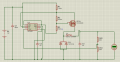
The output voltage is adjusted by the ratio of the resistors 6k8:2k2, and there is always 1.25v across the lower resistor when the circuit is running.
You asked a separate question about the current, the max current is set by the current limiting resistor which connects before pin7 of the IC. I used a 0.18 ohm resistor to set the max current at about 1.75A. A 1.8 ohm resistor would set the current at about 0.175A.
The output voltage is adjusted by the ratio of the resistors 6k8:2k2, and there is always 1.25v across the lower resistor when the circuit is running.
You asked a separate question about the current, the max current is set by the current limiting resistor which connects before pin7 of the IC. I used a 0.18 ohm resistor to set the max current at about 1.75A. A 1.8 ohm resistor would set the current at about 0.175A.
Oops, sorry! I seem to have mis-typed. What I meant to ask is how do you adjust the output current? Is it simply by adjusting the input current? I'm asking because I am looking at getting as much as 3 amps of current at 5 V.
Being a power supply it does not "set" an operating current (apart from the max current limit), the load device that you connect to the power supply draws as much current as it needs.
If you need a power supply capable of 5v 3A this circuit should do it, but you need a decent PFET, and an inductor safe for 3A continuous (which means a 5A rated inductor). The schottky diode is already easily good for 3A.
One of the benefits of this circuit is the 34063 IC is just the "brain", it does not carry any significant current. The main current is only carried by 4 components;
PFET
Inductor
Schottky diode
Current limiting resistor
Hi Sir I would Like to get variable voltage starting from 3 V to 9 VDc, With an input of 12V Dc. With 4 Amp Current limit. If you could provide me with schematics with excellent efficiency It would be really helpful to me. Waiting for your reply
Deepak Kamble
This post is a hijack, trying to take over someone else’s thread as your own. A thread belongs to the OP (Original Poster), and hijacking is not allowed on AAC.
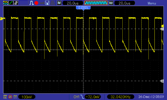
Scope current L1 inductor (on period) at 5v 1.5 amps.
Above is the on period current through the PFET and L1 inductor. As it is a PFET this is inverted so the pointy bit at the bottom is the max current, the top is zero current. At 1.5A and 32kHz the SMPS is very stable, as switching period is reduced becuase the peaks just hit the 0.32v max current limit set by my choice of 0.18 ohm resistor. (However voltage regulation is still the main regulation).
Very interesting read. I have just started into power supply design and I have found that getting SMPS to work is pretty easy... getting them to work properly can be a different story. I have a couple questions.
1) How can you claim that the circuit is stable based on the above plots? I'm missing something. Can you elaborate a bit more?
2) Why no step load plots? This is good indicator of stability although I have found in the past that step load tests do not indicate adequate phase/gain margins (I.E. I've found some of my supplies to have poor phase/gain margins even though my step load tests have shown no oscillations). I'd suggest to maybe determine the phase/gain margins... it's not too hard to couple in an AC waveform to see that you have adequate margins.
3) Did you take your current measurements by simply measuring the voltage over your current limit resistor? I guess you tied your scope ground to the input supply with the negative voltage?
1. My use of the word "stable" was related to the MC34063 IC operation, that is known for being "unstable" at lower currents due to the nature of its fixed on-period and its tendency to go discontinuous.
2. Because I'm lazy. But I did provde scope shots at 3 loads of 1.5A, 1A and 0.5A.
3. No. I placed ammeters before the +Vin terminal and after the +Vout terminal, to give proper operating current measurements.
Please remember this is not really a circuit that I have designed, it's a standard circuit from the MC34063 datasheet that previously used an external PNP switching device.
What I did was to substitute a PFET directly into their circuit with a few tweaks to parts values, and then show the circuit operates normally and the PFET increases running efficiency (and overall power) due to the lower ON voltage of the PFET compared to a PNP bipolar transistor.
So the goal was to swap the PNP for a PFET and prove it still works, and also works better.
@THE_RB
hi, i need to bring up this thread, to ask something.....
what is the effect on efficiency numbers with and without p-channel mosfet ( the simple configuration of post 8 ) ? lets say i will connect it to some load of 500mA where yours has shown 95% efficiency.
and thanks for this wonderful thread, very helpful.
It'll lose much more power. if your load is 5V, 1Amp and input is 12v then 7805 eats (lose) 7 watts and load eats 5 watts (12watts total). if we use switching regulator like this one then we can save 7 watts in this condition.
Hy I know this is a very old article but I found this just a few days ago when I was looking for a simple design for a buck converter.
So I tried the design on a bread board but I get 11.7v output 12.4v input. I'm just a beginner hobbyist so tried to build it a few times but get the same result.
Back tracing with a multimeter from the output lead me to believe that I'm doing something wrong with the p mosfet. I get 11.7 and 12v on all three pin. Is this right or am I missing something.
This was an interesting thread for me because i had looked into beefing up run of the mill buck regulator chips myself a few times and this particular chip i meant to do something with too, i even ordered some a few years back.
The only thing i dont like about the chip being used is the operating frequency. According to this thread, it's around 26kHz, which is quite low in today's world of switching regulators except of course for PC computer power supplies. I had been working at 50kHz and up but that was with a different chip and that allowed me to keep the inductor value lower, like 50 to 100uH.
If i get a chance i'll breadboard this circuit and see what comes of it.

 Facebook
 Google
 GitHub
 Linkedin