 Facebook
 Google
 GitHub
 Linkedin
Here is a circuit I have successfully built for float-charging 12V Sealed Lead-Acid Batteries (SLAs). With minor tweaks, it can also be used as a float-charger for 12V flooded-cell automotive batteries. It is a variant of a circuit that is posted in several places on the Web, but with some better features, analysis and description. Note that this charger would require some tweaks to be used between a source of pure DC (regulated supply or solar panel) and a battery.
I use it with a wall-wart (plug-pack) power supply bought at a garage sale, rated at 120Vac 60Hz input, and ~15Vdc 1A output. The exact rating of the wall-wart is not that important, just so it is capable of at least 1A and has an unloaded open-circuit voltage of 17Vdc to 22Vdc. I have seen these with and without an internal filter capacitor, modeled as C1. I will talk about this capacitor more, later.
Float charging any lead-acid chemistry battery is first about controlling the initial in-rush current (to protect the power supply, the regulator, and the battery) when a mostly discharged battery is initially connected to the charger. Second, after the battery accumulates charge, and its terminal voltage rises, the regulator must hold the battery voltage constant at the correct float voltage. The correct float voltage (at any given temperature) for Lead-Acid batteries ranges from ~13.0V to ~13.7V. Consult the maker's recommended float voltage for your specific battery.
The attached circuit does both. The initial charge-up current is limited by the choice of C1 and the current-limiter circuit consisting of Q1, R4 and R5. The capacitance of C1 determines the ripple at V(Plus). Ideally, it will big enough so that after the battery is charged (reaches the float voltage), the voltage at the input of the LM317 regulator will stay above 13.7+Vdo (>~15.5V) so that the battery sees no ripple in the steady-state. If C1 is small enough, then during the initial charge-up, the voltage at V(Plus) will sag so that the regulator drops out of regulation, further limiting the initial charge-up current.
The current limiter consisting of Q1, R4 and R5 puts an upper bound of about 1.2A on the instantaneous charging current. It does this by pulling-down on V(a) (the adjustment terminal on the LM317), thereby reducing the voltage at the LM317 output. It does this cycle-by-cycle during the time when there is a lot of ripple on C1. Because of the ripple across C1, even though the peak current is set by the limiter is 1.2A, the average maximum charge-up current is held at about 0.7A, which limits the dissipation in the LM317 and prevents overheating the wall-wart. A TO220 version of the LM317 gets hot to the touch, but not excessively so...
I also place diode D1 between the regulator and the battery positive terminal to prevent the battery from discharging backwards into the voltage sensing network (R1, R2 and R3) in the event that the wall-wart is unplugged or loses AC power. This slightly degrades temperature compensation, and requires that the float voltage be adjusted if the ambient temperature strays from 25deg C. This eliminates the necessity for a reverse protection diode from LM317 output to input, usually shown other places...
Some DC Wall-Warts have C1 internal to the package; some have just the full-wave bridge with no filtering at all. If the intrinsic filter capacitor is non-existant, or too small, add one at the input of the LM317 to control the ripple as shown in the simulation:
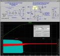
In the simulation, I came up with models for the Wall-Wart Power Supply, the regulator/current limiter, and a lead-acid battery. The battery constants were chosen so that the simulation runs in 20s instead of several hours it might take to charge a battery. The plot upper panel shows the battery voltage V(bat+) (starting from 12V). The lower panel shows the min/max ripple voltage V(plus) and the pulsing (due to ripple) charging current. Note that in the steady-state, the charging current becomes smooth. If C1 is too big, the ripple ceases too soon. If it is too small, then ripple would persist even after the battery reaches a charged state...
The second set of plots zooms into a region where the 120Hz ripple across C1 is helping to limit the current. The light blue trace I(D1) shows the effect of the both the ripple across C1 and the effect of the active current limiter. The dark blue trace V(a) shows Q1 controlling the voltage at the adjustment terminal of the LM317.
I use it with a wall-wart (plug-pack) power supply bought at a garage sale, rated at 120Vac 60Hz input, and ~15Vdc 1A output. The exact rating of the wall-wart is not that important, just so it is capable of at least 1A and has an unloaded open-circuit voltage of 17Vdc to 22Vdc. I have seen these with and without an internal filter capacitor, modeled as C1. I will talk about this capacitor more, later.
Float charging any lead-acid chemistry battery is first about controlling the initial in-rush current (to protect the power supply, the regulator, and the battery) when a mostly discharged battery is initially connected to the charger. Second, after the battery accumulates charge, and its terminal voltage rises, the regulator must hold the battery voltage constant at the correct float voltage. The correct float voltage (at any given temperature) for Lead-Acid batteries ranges from ~13.0V to ~13.7V. Consult the maker's recommended float voltage for your specific battery.
The attached circuit does both. The initial charge-up current is limited by the choice of C1 and the current-limiter circuit consisting of Q1, R4 and R5. The capacitance of C1 determines the ripple at V(Plus). Ideally, it will big enough so that after the battery is charged (reaches the float voltage), the voltage at the input of the LM317 regulator will stay above 13.7+Vdo (>~15.5V) so that the battery sees no ripple in the steady-state. If C1 is small enough, then during the initial charge-up, the voltage at V(Plus) will sag so that the regulator drops out of regulation, further limiting the initial charge-up current.
The current limiter consisting of Q1, R4 and R5 puts an upper bound of about 1.2A on the instantaneous charging current. It does this by pulling-down on V(a) (the adjustment terminal on the LM317), thereby reducing the voltage at the LM317 output. It does this cycle-by-cycle during the time when there is a lot of ripple on C1. Because of the ripple across C1, even though the peak current is set by the limiter is 1.2A, the average maximum charge-up current is held at about 0.7A, which limits the dissipation in the LM317 and prevents overheating the wall-wart. A TO220 version of the LM317 gets hot to the touch, but not excessively so...
I also place diode D1 between the regulator and the battery positive terminal to prevent the battery from discharging backwards into the voltage sensing network (R1, R2 and R3) in the event that the wall-wart is unplugged or loses AC power. This slightly degrades temperature compensation, and requires that the float voltage be adjusted if the ambient temperature strays from 25deg C. This eliminates the necessity for a reverse protection diode from LM317 output to input, usually shown other places...
Some DC Wall-Warts have C1 internal to the package; some have just the full-wave bridge with no filtering at all. If the intrinsic filter capacitor is non-existant, or too small, add one at the input of the LM317 to control the ripple as shown in the simulation:
In the simulation, I came up with models for the Wall-Wart Power Supply, the regulator/current limiter, and a lead-acid battery. The battery constants were chosen so that the simulation runs in 20s instead of several hours it might take to charge a battery. The plot upper panel shows the battery voltage V(bat+) (starting from 12V). The lower panel shows the min/max ripple voltage V(plus) and the pulsing (due to ripple) charging current. Note that in the steady-state, the charging current becomes smooth. If C1 is too big, the ripple ceases too soon. If it is too small, then ripple would persist even after the battery reaches a charged state...
The second set of plots zooms into a region where the 120Hz ripple across C1 is helping to limit the current. The light blue trace I(D1) shows the effect of the both the ripple across C1 and the effect of the active current limiter. The dark blue trace V(a) shows Q1 controlling the voltage at the adjustment terminal of the LM317.
Attachments
-
 136.7 KB Views: 412
 -
 107.8 KB Views: 262


