12V DC to 31V circuit dropping below protection voltage when lights come on

sghioto

Joined Dec 31, 2017
8,737
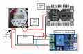
Test mode steps:
1. Disconnect lead from +battery.
2. Connect jumper wire (shown in blue) from + BAT to + OUT of the module
the module is now effectively bypassed using the jumper.
3. Set Return ON to below the nominal battery voltage that was measured with the LEDs ON.
4. Reconnect lead to +battery
System should power up. After the battery voltage recovers and rises above the Return ON setting the module should activate.
5. remove jumper.

If this works as I suspect the jumper can be replaced with a P channel mosfet circuit or an additional relay module to operate automatically.


1734292060962.png
 
Last edited:

Thread Starter

richardeblack

Joined Dec 13, 2024
14
Test mode steps:
1. Disconnect lead from +battery.
2. Connect jumper wire (shown in blue) from + BAT to + OUT of the module
the module is now effectively bypassed using the jumper.
3. Set Return ON to below the nominal battery voltage that was measured with the LEDs ON.
4. Reconnect lead to +battery
System should power up. After the battery voltage recovers and rises above the Return ON setting the module should activate.
5. remove jumper.

If this works as I suspect the jumper can be replaced with a P channel mosfet circuit or an additional relay module to operate automatically.


View attachment 338033
Thank you very much for this suggestion.
I will not be able to try this out for a few days as I have got the unit in place working the lights and just have to check they are coming on each day (a bit annoying but doable).
When I get a chance to try it I will get back to you. I'm not sure how the relay or MOSFET circuit is driven but I'm sure you will make it clear. I'll let you know when I've tried it out.
Thank you very much.
 

Thread Starter

richardeblack

Joined Dec 13, 2024
14
Thank you again sghioto
I have tried the shorting the reset pins which I take it are just connected to input +12 and output +12V? This resets it if it has tripped when the timer activates. I have fitted a momentary switch to do this which works although it means I have to nip down to the lights to activate it when the battery is low.
What I have found is that it is the boost unit that trips the protection unit. If I disconnect the lights, reset with the link, then connect the light string the unit doesn't trip. I assume this means that it is the boost unit that is causing the problems. I have tried a smaller one to no avail. I guess charging the capacitors causes the problem. I am thinking of running the boost unit direct from the battery and using the timer relay to switch the 31V output to the lights. The boost unit doesn't draw much current with no output draw so shouldn't be a problem.
I hope that makes sense. Does it sound like a sensible work round to you please?
Thank you very much
Richard
 

sghioto

Joined Dec 31, 2017
8,737
I figured it was the boost unit as they usually all have a high although brief in rush current.
My plan was to replace that momentary switch with a transistor or relay to perform that function.
Connecting the boost directly to battery will work but does drain the battery when the Timer is OFF.
If that's not an issue then your suggestion is fine.
 

Thread Starter

richardeblack

Joined Dec 13, 2024
14
I figured it was the boost unit as they usually all have a high although brief in rush current.
My plan was to replace that momentary switch with a transistor or relay to perform that function.
Connecting the boost directly to battery will work but does drain the battery when the Timer is OFF.
If that's not an issue then your suggestion is fine.
Thank you so much. I will check how much the boot unit draws with no load. I am interested in your idea about using a transistor for the reset, thus automating it but wonder what will happen when the voltage drops below the cut off and shuts the circuit down? Will it then activate the reset causing the lights to flash on and off? Sorry to be dim.
Thank you for persevering with trying to help me.
Richard.
 

sghioto

Joined Dec 31, 2017
8,737
but wonder what will happen when the voltage drops below the cut off and shuts the circuit down? Will it then activate the reset causing the lights to flash on and off? Sorry to be dim.
It would not as the momentary transistor switch would be connected to output side of the Timer relay contact.
Once the Timer shuts off power is disconnected from the switch.
I see that the Timer and Low battery module also connected directly to the battery. Wonder how much current that draws during the day.
 

MisterBill2

Joined Jan 23, 2018
28,043
Could you get away with faking a soft start of the boost circuit?? Thru a resistor for a few seconds, then direct? A two step timer switch, maybe?? OR, switch on the boost portion and then switch on the load? That could be just a mosfet switch going from full off to full saturated in five seconds or so.
 

Thread Starter

richardeblack

Joined Dec 13, 2024
14
It would not as the momentary transistor switch would be connected to output side of the Timer relay contact.
Once the Timer shuts off power is disconnected from the switch.
I see that the Timer and Low battery module also connected directly to the battery. Wonder how much current that draws during the day.
Thank you yet again
I will check again but am fairly sure they draw about 10ma. I will have a go at that reset circuit and will then rewire it so that the timer relay feeds the low voltage cut off circuit input then the output from that feeds the boost supply. I guess the timer relay coil will be fed direct with the contacts fed from the battery to the input of the voltage cut off unit? I'll do some experimenting with a spare set of components.
Thank you.
 

Thread Starter

richardeblack

Joined Dec 13, 2024
14
Could you get away with faking a soft start of the boost circuit?? Thru a resistor for a few seconds, then direct? A two step timer switch, maybe?? OR, switch on the boost portion and then switch on the load? That could be just a mosfet switch going from full off to full saturated in five seconds or so.
Thank you for your thoughts.
The load doesn't cause a problem, just the boost unit which. I think the idea of the mosfet switch taking 5 seconds or even less might work. I'll have a go at that as well.
Thank you.
Richard
 
Top