 Facebook
 Google
 GitHub
 Linkedin
Hello,
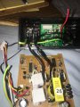
I was recently “doing my thing” which consists of disassembling various electronics to
See what’s inside, how things work, etc.
I came up with this plan to extend the wiring on my power inverter. I marked all wires then snipped them need the middle of each wire. I then connected each end to a 12”-20” wire
Thereby extending all the connections to allow an external outlet, and extended power control button. Basically everything I did was rather pointless but it was entertaining and interesting to do.
My only question is, is this safe? Probably should’ve figured that out first but got caught up in doing it that I didn’t research.
I have tested the unit seems to not deliver enough power to run certain things. (Game console) and the USB Outlets are not working properly. (Hit or miss)
I am wondering if it’s possibly the fuse? If I understand correctly the fuse needs to be above but as close to the current drawn through it as possible ?
What fuse would be appropriate?
Attachments
-
 256 KB Views: 9
 -
 258.7 KB Views: 8


