 Facebook
 Google
 GitHub
 Linkedin
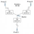
I am trying to build a hall effect based voltage sensing system.
http://www.ebay.com/itm/New-5A-20A-...Pi-UNO-/112275500486?var=&hash=item1a24242dc6
Please see the attached sketch i made.
I am asking for suggestions on a different source for the hall effect sensor. My current design only has a 42.5mA peak assuming 120V RMS, and the sensor full scale is 5A.
I am asking if anyone knows of a chip that maybe has full scale of +/- 50mA to get better resolution.
I don't want to decrease my resistance as I would like my voltage sense system not to consume to much power or get to hot.
The goal is to feed the isolated signal to an Arduino or RasperryPi without having a Potential Transformer. I targeted my resistors to have about the same current draw as the magnetizing current of 3 PTs
thank you for your time and have a good ay
Attachments
-
 11.7 KB Views: 16


