I don't know why you have 6 LEDs in a string, when I have informed you that you are limited to 5 LEDs in a string.
It will not work well at all with 6 LEDs.
You must cut back to 5, or increase your supply voltage.
LEDs must have the current flow through them limited by some mechanism, either active or passive.
Your LEDs have a typical Vf of 2v at their rated current.
12v/2 = 6, but that does not leave any voltage to drop across a resistor. If you tried to power them directly from 12v, they would start to warm up, and as they warm up, their Vf decreases. This causes the current through them to increase, which makes their Vf even lower. Pretty soon they get so hot that they burn up.
A good rule of thumb is to start out by subtracting 10% from your supply voltage, and then divide the result by the typical Vf of your LEDs. Throw away the fractional portion, and you have the maximum number of LEDs that you can use in a string.
I have no problem using 5 LED strings but I was just reviewing the other posts and the power supply that was suggested is 15V, I thought that it was 12V. According to the above calculations this will allow me to use 6 LEDs per string, am I correct on this?
OK, you're doing it right. Sorry, I just have a lot of threads that keep changing pace.
When you are calculating for resistance, use:
R >= (Vsupply - (Vf_LED * LED_count)) / Desired_Current
Notice the ">=" sign? You must use a resistor that is >= than the result, or you will shorten the life of the LEDs.
Here is a table of standard resistance values: http://www.logwell.com/tech/components/resistor_values.html
Bookmark that page.
Use the green columns (E24 values). You can use the higher series, but you'll pay a good bit more for the resistors, and you will definitely have to order them.
Note that 130 Ohms is the closest E24 value that is >= 125 Ohms.
Then you calculate using the new value of R to get the LED current:
3v/130 = 23.1 mA - close enough.
Then calculate the resistor power requirement, and double it for reliability:
3*.0231 * 2 = 138.5mW. You could get by with 1/8 Watt resistors (125mW), but 1/4 Watt is suggested.
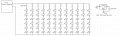
(12) 130 Ohm, 1/4W Resistors
(72) 2V, 24mA LEDs
(1) 15V, 0.8A Desktop Power Supply + power cord
as well as the wire.
To test the LEDs I can use a LM317 Current Regulator.
I have attached a final schematic that I believe to be correct.
EDIT** I left out the LED in the schematic for the testing device but it would go between the voltage source and the IN pin of the LM317, also the resistors should be 130 Ohm as opposed to 125 Ohm
Actually, that's not the way you calculate the current for an LM317.
R ~= 1.25/Desired_Current, where 10mA <= DesiredCurrent <= 1.5A
Conversely,
I ~= 1.25/R, where 0.833 <= R <= 125 Ohms.
You want about 23.1mA current through the LM317 to test the LEDs, so:
R ~= 1.25/23.1mA = 54.11 Ohms.
We're back to the non-standard resistance value thing again.
However, looking at our tables... http://www.logwell.com/tech/components/resistor_values.html
...we see that 56 Ohms is a standard value. Let's try it.
I ~= 1.25/56 = 22.3mA. That's going to be close enough for your purpose.
Also, you don't want to connect the IN of the 317 to +V and the ADJ to GND at the same time, or you'll just be warming up the 317 without really doing anything.
Truth, the original test schematic would work well, but this is a good design too. I've come up with quite a few current regulators (ie, constant current source). When I mentioned the voltage regulated power supply it eliminates the need for current regulation (you need to regulate one or the other).
Because the do something visible, they are pretty fun. They aren't that hard to use either, the math is pretty much simple algebra.
I have never been on any other forum where people replied so quickly and were so willing to help. I just wanted to say thank you to everyone that has helped me, in particular, SgtWookie and Bill_Marsden. I feel like I have a jump start on my DC Circuits class coming up next semester!! haha
I have decided that I would like to control 6 of the LEDs with photo resistors...I believe that I have to hook the LEDs up in parallel so that I can dim each LED separately (I may be completely wrong about this). So far here is what I have determined:
Using the same 15V power supply as well as the same 2V, 24mA LEDs.
Resistor:
R = (15V-2V)/24mA
R = 13V/24mA
R = 542 Ohm
I believe that the closest standard resistance value is 560 Ohm.
13V/560 Ohm = 0.0232 --> Pretty close to 24mA
13 * 0.0232 * 2 = 0.6032 --> I should probably use 1W Resistors
I have attached a schematic as well....I may be COMPLETELY wrong about this so any help would be greatly appreciated.
You could just one photocell, but my 1st question is why?
It would work, sort of. LEDs don't light linearly to current. One the other hand, depending on what you're trying to accomplish, this may be exactly what you are wanting.
Photocells vary between several 100Ω (maybe a bit less) to several megohms. The LEDs will light only when there is light, and not very brightly since the photocells are not switches. There are ways using BJT transistors to make the switch cleaner.
This is off topic from the OP post. I have an article on possiblities I posted earlier, LEDs, 555s and light chasers article. Wookie has posted some chips here and there to replace the transistors.
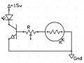
These LEDs/photo resistors are going to be underneath plexiglass cup holders....such that when you set a cup on them the LED dims (or goes off) and when you pick the cup up the LED brightens. I want each LED to be able to dim/brighten individually without changing the other 5 LEDs
I apologize for my ignorance when it comes to circuitry but am I only supposed to pay attention to the first half of the schematic? The part utilizing the transistor. Or will the 555 Timer also be used?
The transistor section is what I was referring to, since I mentioned it can be used as a switch. Just tie the collector to the LED/Resistor, and it will be a lot more reliable than the idea you proposed. The pot sets the light level it switches on.
The 555 version will be completely on or completely off, no in between, and will drive the LED by itself. I recommend the transistor version for your idea though.
One other point, you can use the pot to find the resistance you need, then eliminate it and replace it with fixed resistor.
 Facebook
 Google
 GitHub
 Linkedin