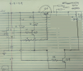
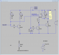
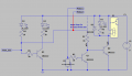
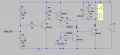
1.5v drop across collector to emitter.

Thread Starter

ulms

Joined Mar 19, 2024
179
Ulms, you should look at the datasheet of the LM555 (or NE555) to see the graph of its output voltage that does not go as high as the power supply voltage, it drops about 1.4V (at a low current).
You should also look at the datasheet of an NPN transistor that shows a 0.6V drop from base to emitter (at a low current).

Then the total 2V of voltage drops results in your output voltage of only 3V to 3.5V.
I'm using the 555 output to turn on Q4. The circuit gets 5v from the supply.
 

Irving

Joined Jan 30, 2016
5,195
What is the purpose of Q1? Why can't you drive the relay with Q4 directly?
View attachment 321683


Because the relay is driven by the moisture(?) sensor probes

However, I agree that I don't see the point of switching the supply to the relay driver pair, it adds no obvious benefit except as a complex way to inhibit relay switching. I'm guessing the 555 turns on for a short period (1sec?) every long period (1 min?) in a bid to save battery volts?

A simple 1 wire change eliminates Q4 entirely, yet inhibits the relay as required...

1714929537309.png
1714929712520.png1714929908745.png

A further simplification removes Q3...

1714933726083.png
 
Last edited:

Thread Starter

ulms

Joined Mar 19, 2024
179
Because the relay is driven by the moisture(?) sensor probes

However, I agree that I don't see the point of switching the supply to the relay driver pair, it adds no obvious benefit except as a complex way to inhibit relay switching. I'm guessing the 555 turns on for a short period (1sec?) every long period (1 min?) in a bid to save battery volts?

A simple 1 wire change eliminates Q4 entirely, yet inhibits the relay as required...

View attachment 321693
View attachment 321694View attachment 321695
Hello Irving, thank you for putting your time into that circuit. I'll review it this evening. Some of my requirements are on 15 sec off 1.5 hours and 0 volts across probes during off.
 

Ian0

Joined Aug 7, 2020
13,226
Makes me wonder if you could put the probes on the RESET input of the 555, and drive the relay directly from its output, eliminating all the transistors.
 

Thread Starter

ulms

Joined Mar 19, 2024
179
Moisture probes collect "trash" and "corrosion". If you only power the probes for a short duty cycle, they last longer.
Yes Ron electrolysis, in one month of 24/7 monitoring ss probes disappeared. And get this the seedling pot they were in was easily 5xs smaller than the none monitored pots.
 

Irving

Joined Jan 30, 2016
5,195
I moved (power to the probe) from +5V to (From_555). I think that removes probe power most of the time. It will leave some small fraction of a volt on the probe.
The problem with that is that the output from the 555 isn't a stable voltage so probe switching point could be impacted.

At the risk of putting bits back, here is a better option... M1 is a low-Vgs p-channel MOSFET; there are loads of suitable parts priced lower than the BJT

1714945348088.png

The ideal solution would be to use AC rather than DC, so no electrolysis occurs - maybe tomorrow I'll sketch something...
 

Thread Starter

ulms

Joined Mar 19, 2024
179
The problem with that is that the output from the 555 isn't a stable voltage so probe switching point could be impacted.

At the risk of putting bits back, here is a better option... M1 is a low-Vgs p-channel MOSFET; there are loads of suitable parts priced lower than the BJT

View attachment 321711

The ideal solution would be to use AC rather than DC, so no electrolysis occurs - maybe tomorrow I'll sketch something...
Wow thank you, I'm about to learn about AC and mosfets!
 

LadySpark

Joined Feb 7, 2024
194
I didn't stutter.
Maybe you need to look at how the change in collector current in parallel to the change of base current in parallel effects gain product. This is why Beta is not constant in a transistor and always will be expressed with test current conditions.
 

Thread Starter

ulms

Joined Mar 19, 2024
179
I didn't stutter.
Maybe you need to look at how the change in collector current in parallel to the change of base current in parallel effects gain product. This is why Beta is not constant in a transistor and always will be expressed with test current conditions.
I always wondered about why so many beta's on data sheet, Thank you.
 

Ian0

Joined Aug 7, 2020
13,226
I didn't stutter.
Maybe you need to look at how the change in collector current in parallel to the change of base current in parallel effects gain product. This is why Beta is not constant in a transistor and always will be expressed with test current conditions.
Nothing to do with the variation in beta. All to do with the fact that one is common-collector and the other is common-emitter.
 

LadySpark

Joined Feb 7, 2024
194
Nothing to do with the variation in beta. All to do with the fact that one is common-collector and the other is common-emitter.
Yes it is, but I didn't state it the same way. But if you want to know, why its the same. Ic MAX on a common collector is B *Ic where Ic Max is Vcc/Rl in this common emitter design the TS ended up with.

So yes, Beta is involved.
 
Top