0mA to 500mA Voltage-to-Current Signal Controller

Thread Starter

swapnil14327

Joined Oct 21, 2013
4
Hello Guys,

I need a help regarding an Op-Amp circuit.

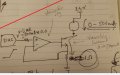
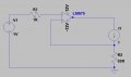
In below page I read about 0-20mA voltage to current conversion from 0 to 5V respectively.
http://www.allaboutcircuits.com/textbook/semiconductors/chpt-8/voltage-to-current-signal-conversion/

I need a similar circuit by which I can increase my output current to 500mA.

I tried the above circuit using LM675. but by 10mA to 15mA the Op-Amp starts heating up, and does not satisfy my requirement,

Can some one suggest me a similar kind of circuit where I can control my output current to 0mA to 500mA with 1mA resolution.

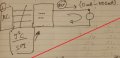
If the above configuration is not possible with Op-Amp, it can also be a non Op-Amp based circuit, I have attached a reference circuit.

Thanks,
 

Attachments

MikeML

Joined Oct 2, 2009
5,444
Need some clarifications:

1. You want the current source to drive a load one end of which is ground?

2. Can one end of the load be connected to +12V (so we actually make a current sink)?

3. What is the minimum resistance of the load (power dissipation in the regulator)?

4. What is the maximum resistance of the load (compliance)?

5. The 500mA current can be drawn from the +12Vdc supply?
 

Thread Starter

swapnil14327

Joined Oct 21, 2013
4
Thanks for the reply,

I think the attached circuit will help to understand more about my problem.

In the below circuit I have connected a MOSFET too...but actually in hardware I havent, I was not sure if it will work with MOSFET.

Problem Statement: I have a inductive load(Rated Current -> 0.5A, Resistance -> 23 Ohm),Which will be connected to either 12V or 24V supply(completely different supply), I want to test this load by passing 0mA to 500mA of current passing through it, in resolution of 1mA.

I am designing the entire circuit standalone(no manual work like adjusting pre-set resistor or input voltage) using any one interface DAC/ I2C / PWM / SPI etc.
 

Attachments

AnalogKid

Joined Aug 1, 2013
12,043
Important:
What is the max. signal frequency?
Does the output stage need to source current, sink current, or both?

Two standard options:
1. Change to a power opamp, one that behaves like a normal opamp but can make 1 A output current. TI (Burr-Brown), Apex.
2. Add a current boost stage to a standard opamp.

National Semiconductor app note AN-31, page 9.

EDIT: more information came in while I was writing. Yes, your circuit should work with a medium power MOSFET. Note that if the current is stopped rapidly there will be an inductive kick from the load that will need to be suppressed.

ak
 

Attachments

Johann

Joined Nov 27, 2006
190
Thanks for the reply,

I think the attached circuit will help to understand more about my problem.

In the below circuit I have connected a MOSFET too...but actually in hardware I havent, I was not sure if it will work with MOSFET.

Problem Statement: I have a inductive load(Rated Current -> 0.5A, Resistance -> 23 Ohm),Which will be connected to either 12V or 24V supply(completely different supply), I want to test this load by passing 0mA to 500mA of current passing through it, in resolution of 1mA.

I am designing the entire circuit standalone(no manual work like adjusting pre-set resistor or input voltage) using any one interface DAC/ I2C / PWM / SPI etc.
Looking at the resistance of 23 Ohm, 12V should be used.
 

AnalogKid

Joined Aug 1, 2013
12,043
In your drawing 3.jpg, what is the update rate of the DAC? How rapidly can the signal into the opamp change from its minimum value to its maximum value? What is the minimum time between updates to the DAC?

And, how did you decide on the LM675?

ak
 

MikeML

Joined Oct 2, 2009
5,444
Here is a prototype:

274.gif

Green trace shows current in the load vs the input control voltage (0-5V).
Lt. Blue trace shows power dissipated in the NFET as the current goes from 0 to 500mA. Note that it will have to be on a large heatsink!
Red trace shows power dissipation in the sense resistor. At 500mA, the voltage across 10Ω results in a max power dissipation of 2.5W.

With the 10Ω sense resistor, you must start with the 24V supply, not 12V as suggested above...
 

MikeML

Joined Oct 2, 2009
5,444
Here is a way of reducing the dissipation and starting from a 12V supply:

274a.gif

The sense resistor is reduced to 1Ω. The input signal is attenuated by 10.

Peak dissipation in the NFET is still 1.5W, so still need a heatsink.
 

Thread Starter

swapnil14327

Joined Oct 21, 2013
4
Here is a way of reducing the dissipation and starting from a 12V supply:

View attachment 91607

The sense resistor is reduced to 1Ω. The input signal is attenuated by 10.

Peak dissipation in the NFET is still 1.5W, so still need a heatsink.
I tried the same thing in LTspice.
Can you tell me what have you used as R1, I took simple resistor of 23Ohm, it is giving me 1mA current..tried with same configuration.

can you share your design file please.

Thanks..
 
Top