0-5VDC Variable Controller

Thread Starter

Miramax

Joined Nov 12, 2006
22
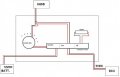
This project is for a motorcycles electronic steering dampener, called the HESD (Honda Electronic Steering Dampener).
The ECU controls the amount of dampening with a linear solenoid via voltage, depending on the acceleration and speed of the bike. 0VDC is no dampening, 5VDC is full dampening. The idea is to be able to switch between automatic ECU control and a manual override at the flip of a switch.
The ECU will fault out if the dampener is not in place, so we need a large resistor between 6-8 Ohm and at least 5W.
(5.75V x 0.85A = 4.88W) measured value
I've used a 6.8 Ohm 10W resistor with good luck, no ECU error-codes.
There may be a more elegant way of doing this, but this way its just simple.
So! We have a 12VDC source that needs to be cut down to 5VDC and be adjustable 0VDC to 5VDC. What would be the best way to do this? I'm not very savvy, so take it easy on me fellas :rolleyes:
 

Attachments

Thread Starter

Miramax

Joined Nov 12, 2006
22
Or maybe I should keep the 7805 regulator in the works as the LM317 is a linear regulator and that it dissipates excess voltage as heat (I'm not sure if the 7805 does this?). If I can cut the voltage down right away to what I expect to max out at, the LM317 wont generate as much heat as if it was working with 11-14VDC
 

kubeek

Joined Sep 20, 2005
5,794
lm317 cannot go lower than cca 1.5V, you have to find some other solution, maybe 7812 + potntiometer and some resistors + transistor in follower mode could do it.
 

Thread Starter

Miramax

Joined Nov 12, 2006
22
lm317 cannot go lower than cca 1.5V, you have to find some other solution, maybe 7812 + potntiometer and some resistors + transistor in follower mode could do it.
Well, It looks like the HESD needs a touch more voltage than 5VDC, word on the street is its max is 5.75VDC... I will confirm later with a meter.
I will do a little homework on what you've mentioned, it may be a better route. :cool:
 

Gadget

Joined Jan 10, 2006
614
Actually, if you bias the adjust pin on a 317 negative with respect to ground, then it will adjust down to zero volts. Taking the ground end of the adjustment pot to something like a -3 volt rail should work fine.
 

kubeek

Joined Sep 20, 2005
5,794
Actually, if you bias the adjust pin on a 317 negative with respect to ground, then it will adjust down to zero volts. Taking the ground end of the adjustment pot to something like a -3 volt rail should work fine.
I think that´s quite hard to achieve on a motorcycle where there usualy is one 6V lead-acid battery.

What supply voltage is available for the device and for the dampener?
 

Thread Starter

Miramax

Joined Nov 12, 2006
22
The motorcycle battery is a 12V lead-acid
The dampener/solenoid runs between 0VDC-5VDC (It may be 5.75VDC, I have yet to confirm)
 

Thread Starter

Miramax

Joined Nov 12, 2006
22
So far this is what I have.. Sorry its a little rough, I'm no Picasso or Tesla ;)


PAD1 is the positive 12VDC from the lead-acid battery
PAD2 is negative
PAD3 is the variable 0-5VDC+ output to the solenoid (HESD)
PAD4 is negative

I haven't figured out the exact values on the caps and resistors quite yet.. I'm sure I will need somebody to hold my hand through that. I do not want the output of the LM317 to exceed the 5.75VDC

I'm told, when external capacitors are used with any IC regulator it is good practice to add protection diodes to prevent the capacitors discharging back into the regulator in the event of abnormal operating conditions, like a sudden short circuit on the input or the output, or a back emf from an inductive load. That is the function of D1 and D2.

The LM3914 will drive the LED bar graph so we know how many volts are at the output (PAD3)

R2 is the pot used to control the output voltage

C1 is a ceramic capacitor. This will go across the incoming power leads and smooth out any ripples before it enters the regulator
C2 is a polarized aluminum or tantalum capacitor. This will go across the output leads, and give a smooth buffer effect when the output is adjusted. One can use larger capacitors for a larger buffer although anything over 10 uF is probably overkill.

C3 and C4 are two capacitors keep things stable, C4 smooths out rapid changes and spikes in the input signal, and C3 keeps the levels from being distorted by spikes when LEDs turn on and off.
 

Thread Starter

Miramax

Joined Nov 12, 2006
22
I am told, that pin 6, pin 7 and pin 8 of the LM3914 as shown set its full scale input voltage to only 1.28V. Pin 6 and pin 7 need to have two resistors in series to ground with pin 8 connected between them to set the full scale voltage higher. Pins 7 and 8 are like an LM317 adjustable voltage regulator.

When all LEDs are on (2.0V red LEDs) and the supply voltage is 13.1V, the LM3914 will dissipate about 1110mW and will be very hot. Its absolute max dissipation is 1365mW but less in a hot environment. A power resistor should be added in series with the group of LEDs to share the heat. Then the anodes of the group of LEDs need a bypass capacitor to ground.
Does this sound right? This is my first time using the LM3914 :rolleyes:
 

Thread Starter

Miramax

Joined Nov 12, 2006
22
Well! I have done a bit of homework on the ways of PWM and it looks like I'm going to junk the linear regulator idea and put a PWM circuit together using a 555 timer.
It looks like I will have to do some trial and error testing and see how the solenoid will react to PWM or if it even works with PWM for that matter..
I have not ran across any information in regards to controlling a linear solenoids position with PWM. The only thing I seem to find is motor speed control...
Anyone know where one might find some information on PWM and solenoids?
I don't know how to figure the inductance issue out, other than trial and error.. Thanks again :)
 
Top