 Facebook
 Google
 GitHub
 Linkedin
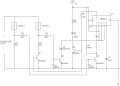
I needed to make a Privacy-Timer control for 2 phones working over the same pot line and this thing seems to work.
The idea of the circuit is:
"Phone A" is private, when "Phone A" is off-hook "Phone B" doesn't have line.
"Phone B" is time controlled, when "Phone B" is off-hook the timer prepares to cut the line to itself in 60-90 seconds.
I have a beginner-to-intermediate knowledge of electronics, knowing a bit of all with many holes.
I want to design circuits, this is the first attempt to do it. With some
measurings and experimentation I get this thing working, but I know that it is far from be a real device, however I wanted to apply basic knowledge (555 timer, voltage divider, transistor as a switch) and solve the problem.
The design comprises 2 main blocks:
1) OFF-HOOK DETECTOR
When a phone is off-hook, it creates a voltage divider with the R68.
With this small voltage (the minimum needed to saturate the transistor)
the current across the 39K resistor switches the transistor.
2) TIMER
With a 555 astable multivibrator.
When both phones are on-hook the 555 is in its ON mode (capacitor charging).
When "Phone B" is off-hook the 555 begin its OFF mode, by connecting to GND the capacitor through another transistor.
While "Phone A" is off-hook the 555 is kept reset, then cutting the line to the "Phone B".
I can't use the voltage of the line to power the timer. The circuit seems to eat too much power even removing the LED circuit.
But, I'm not sure about the inclusion of the external 9V Vcc source.
I want to know your wise opinion about my solution.
Attachments
-
 73.6 KB Views: 61


