question about an oscillator circuit and a rectifier!

Thread Starter

sndpgr

Joined Jun 22, 2006
23
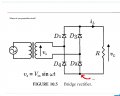
A simple bridge rectifier with diodes,no problems with that! but where do I ground it? what I want to do is , take input waveform on one of the channels of Cro and rectified waveform on another.

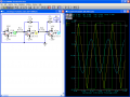
Another picture is of a simple phase shift oscillator, how do i make it oscillate,a trigger at the input???
expecting replies.
I know these are stupid questions , I feel like a moron already!:confused:
 

Attachments

Thread Starter

sndpgr

Joined Jun 22, 2006
23
Thanks.
In the oscillator ckt. do you mean if at the output I will get a signal(across a resistor),assuming I have given supply to the op amp.

About the rectifier will there be any output without CRO's, isn't the whole ckt floating one.
 

Wendy

Joined Mar 24, 2008
23,421
Actually gain is extremely critical for this ocsillator, but the solution is extremely old and simple. A light bulb, in this case low voltage and current, acts as a negitive resistance. The more signal on it the hotter it gets and the more resistance it has. Make it part of an attenuator circuit in the feedback loop and it will control the gain of the amp to produce a really respectable sine wave. I don't remember the circuit off the top of my head, but I'll research it. A Wien Bridge Oscillator has the same problem, and uses the same solution, so this could give you something to work on.

Here is a simple circuit I came up with around 20 years ago that is pretty similar, it uses phase shift of 90 degrees per RC. The sine wave isn't pure, but pretty close.


As to the power supply circuit, you can ground either side, depending on whether you need a plus or minus power supply. For op amps I would use the following version (a plus and minus power supply)...


Thread Starter

sndpgr

Joined Jun 22, 2006
23
Thanks for your replies!
And about the oscillator Bill posted, I still can't figure out how there is an output without an input.My oscillator basics are very bad.
If I want to do that circuit in real will I get an oscillating wave just like that.
I am very confused, and I need to understand oscillators.
Could anybody please post the simplest oscillators you can think off.
 

veritas

Joined Feb 7, 2008
167
The "input" to your oscillator is the feedback loop. Upon power up, there will be enough noise to start the oscillation.
 

Wendy

Joined Mar 24, 2008
23,421
Same thing that causes an amplifier microphone / speaker squeal, there is enough ambient noise that starts the ball rolling, and positive feedback takes it from there (what Veitas said). The feedback loops on the amps we've been discussing only favor one frequency, and attenuate the rest, so you get a pure waveform, a sine wave. The way they favor one frequency differs though widely though, the Wien bridge is a combination low pass and high pass filter, which creates a bandpass. It is the basis of a lot of active filters, where the gain of the amp flips some of the dynamics where the simple RC filters emulate a LC filter.

Some form of positive feedback is absolutely required for all oscillators, no matter what the waveform. and a general rule of thumb the gain always has to be greater than unity (greater than 1). I mentioned gain was critical, too much gain and the sine wave is severely distorted, clipped on the top and bottom. Many applications need a pure waveform, you can make a basic square wave oscillator much easier, so the gain compensation I mentioned with the light bulb is necessary. The light bulb starts off cold so the gain is higher, adjusts the gain of the circuit lower as it heats up. There are other ways to vary gain in a circuit, the light bulb is easy and good enough.

BTW, there really aren't stupid questions, we all start somewhere. If you don't ask you don't learn. Stupidity is terminal, ignorance is curable. You'll find people here are a pretty friendly bunch.
 

Thread Starter

sndpgr

Joined Jun 22, 2006
23
The rectifier is working now .
since I am simulating the oscillator on a schematic so,I don't know how do I get the noise from, so it's on hold for now. Though it would have been nice to see the results though! At least I understood the principle.
Thanks everybody for helping me out!:)


SgtWookie

Joined Jul 17, 2007
22,230
Like Bill intimated, you can use an "initial condition" SPICE command to set the input node near Vee or some arbitrarily high voltage near Vcc/Vdd. That'll get it going - just as long as it's away from zero.

See the attached image. Just to the right of C2, I added an initial condition command to set that node to 8v when the simulation started. The O-scope snapshot on the right was taken from around 5.5 seconds into the simulation.
 

Attachments

Top