 Facebook
 Google
 GitHub
 Linkedin
The problem is the following:
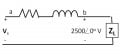
The steady-state voltage drop between the load and the sending end of the line is excessive. A capacitor is placed in parallel with the 250 kVA load and is adjusted until the steady-state voltage at the sending end of the line has the same magnitude as the voltage at the load end, that is 2500 V (rms). The 250 kVA load is operating at a power factor of 0.96 lag. Calculate the size of the capacitor in μF if the circuit is operating at 60 Hz.
I attached a picture of the circuit. Resistor is 1 Ω and inductor's impedance is 8j Ω.
I spent more than 2 hours on this problem and still I cannot figure out the solution.
First of all, I think the wording is unclear. What exactly does this part mean: "[The capacitor] is adjusted in until the steady-state voltage at the sending end of the line has the same magnitude as the voltage at the load end"?
Which exactly is the load end and which is the line end? If the two ends have the same voltage, doesn't this mean that the voltage across the load is zero?
Anyway, this is what I've done so far:
A power factor of 0.96 yields an angle θ = 16 degrees.
I supposed that after adding the capacitor, the voltage across the load becomes \(\tilde{V}_{L}\) = 2500\(\angle\)0.
(I use the ~ accent for the rms value.)
I found the complex power \(S = 250\angle 16\) kVA using θ.
Then using \(S = \frac{|\tilde{V}_L|^2}{Z_L}\) I calculate the impedance of the load \(Z_L = 25 \angle (-16)\).
I plugged this in the equation for the equivalent load impedance after adding the capacitor: \(Z_{eq} = \frac{Z_C Z_L}{Z_C + Z_L}\) (since we know f = 60 Hz, we can find ω and from that \(Z_C\)).
So I found one expression for \(Z_e_q\) with C in it.
I also know that, using voltage divider, \(\tilde{V}_L' = \frac{Z_e_q}{Z_e_q + Z_a_b} \tilde{V}s,\) where \(Z_a_b\) is the equivalent impedance of the resistor and the inductor.
So here's one problem. We are not given a value for \(\tilde{V}_s\). So I assumed it is just known.
From this equation I solved for \(Z_e_q\) and found an expression with no C in it.
So I equated the two expressions for \(Z_e_q\) and tried to solve for C, but a very messy expression came out, and I didn't even try to continue... I have feeling that C is going to be a phasor!
So, what went wrong? Thank you very much for your help.
Attachments
-
 9.9 KB Views: 50


