Zippy microswitches in lieu of potentiometer?

Thread Starter

Dcandpc

Joined Nov 24, 2021
8
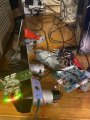
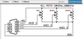
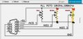
Hi all sorry for the long winded green horn question. Any feedback would be greatly appreciated. I am building a custom gear shifter out of my old Logitech g27 steering wheel. It is all powered up and functioning correctly, but I am trying to use the zippy click microswitches from the left and right paddle shifters to work off of the three wires that run from the motherboard to the brake and clutch pedals which is are controlled by a potentiometer switches . I can not get this micro switch to function when hooked up correctly to the wires for the potentiometer. I can get it to function when I hook the three wires up incorrectly, but it cuts the power to the wheel/unit when I press the switch but does register in my controls of the game I am trying to configure this with. problem is it pauses the game when the power cuts out to the unit when micro switch is depressed. Is there a way to use these zippy click style micro switches donated from the paddle shifters to make function off of the three wires for the potentiometer switches(brake and clutch pedal) ? I believe it is a zippy brand sm1 click style microswitches and the potentiometer p/n is 103870-1000 Thank you for your help in advance
 

Thread Starter

Dcandpc

Joined Nov 24, 2021
8
Here’s a picture of the dissected g27 steering wheel. It is functioning and factory controls are communicating with my computer properly. Second picture is of the two click style microswitches I am trying to make operational by using the power leads for the potentiometer switch for the brake pedal activation which I have attached in the third picture. The only time I can make these microswitches work, it causes the power to cut out on the unit while the microswitch is being activated and comes back on immediately once released?? Sorry I am green horn at this and I appreciate your efforts !
 

Attachments

Thread Starter

Dcandpc

Joined Nov 24, 2021
8
Of course this mess is just for testing purposes only and will be fixed and installed properly if I can get this to work
 

Thread Starter

Dcandpc

Joined Nov 24, 2021
8
The switches will be mounted on a gear shifter if I can make them work.I unplugged the wires from axis two and axis three potentiometers and plugged them in to my microswitches. Green, 5v, ground to one snap button microswitch, white, 5v, ground to the second microswitch
 

shortbus

Joined Sep 30, 2009
10,045
The only time I can make these microswitches work, it causes the power to cut out on the unit while the microswitch is being activated and comes back on immediately once released
Stop and think about this. You use of the micro switches makes you controller think it has either a short circuit or open potentiometer when activated. Those pots are used to make the controller do what a car does in real life, turn a moving, variable input into a simulation electronically. When you substitute the switch for the pot it would be like slamming on the brakes or applying full throttle instantly in a car.

You will need another approach to make a paddle shifter, not the game controller your using now. A way will need to be made to make each push of the paddle to count up then back down as needed.
 

GetDeviceInfo

Joined Jun 7, 2009
2,196
Stop and think about this. You use of the micro switches makes you controller think it has either a short circuit or open potentiometer when activated. Those pots are used to make the controller do what a car does in real life, turn a moving, variable input into a simulation electronically. When you substitute the switch for the pot it would be like slamming on the brakes or applying full throttle instantly in a car.
I think thats his intention, as in zippy
 

LesJones

Joined Jan 8, 2017
4,188
I suspect you are shorting out the 5 volt supply. UNTIL YOU DRAW A SCHEMATIC OF EXACTLY YOU HAVE THE SWITCHES CONNECTED we can only guess.

Les.
 

dendad

Joined Feb 20, 2016
4,474
You could try NC to +5V, NO to gnd, and COM to the signal wire.
But the circuit may require some resistance to work.
So, add a series 10K resistor from the COM to the signal wire.
As requested, you need to draw a circuit of how you connected the switches. Your photos are not cleat enough.
 
Top