Zero crossing using PIC18F45K50

Thread Starter

Qual

Joined Aug 5, 2016
48
Hi all,

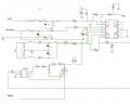
I am using PIC1845K50 to control fan and i want to start controlling PWM signal whenever PIC detects the zero.
As per data sheet there is no zero crossing facility by this micro controller.
Can any one suggest me how to do this in coding with out any extra hardware.
 

AlbertHall

Joined Jun 4, 2014
12,345
Can any one suggest me how to do this in coding with out any extra hardware.
It depends what hardware you already have. The pic will need some representation of the AC supply waveform to be able to determine the zero crossing point.
 

MaxHeadRoom

Joined Jul 18, 2013
28,619
See the Fairchild app note AN-3006.
As already mentioned you will need some way of monitoring the AC waveform for zero crossing.
How do you intend controlling the AC waveform with PWM?
Max.
 

Thread Starter

Qual

Joined Aug 5, 2016
48
well i am using resistive circuit to bring down the AC voltage and then feeding to a op amp (using differential amplifier)
the output of the op amp is connected to the analog pin of pic.

Here i am using traic to control the PWM signal...

But through coding i want to detect zero crossing and then start pwm signal controlling through triac.
 

AlbertHall

Joined Jun 4, 2014
12,345
well i am using resistive circuit to bring down the AC voltage and then feeding to a op amp (using differential amplifier)
the output of the op amp is connected to the analog pin of pic.
So what is the voltage on that analog pin at the AC input zero-crossing point? Then just wait until the adc gives that reading.
If you don't know that voltage then we will need the schematic to be able to work it out for you.
 

Thread Starter

Qual

Joined Aug 5, 2016
48
Well the voltage on ADC pin will be within 0 to 5 V and i want to start controlling PWM once pic detects zero crossing...

Now this op amp based Differential amplifier with resistive circuit ( Values are in Mega ohms) is used to bring down AC voltage to mV and then fed to op amp to give differential output.

So Voltage on ADC pin is within 0 to 5V.
 

AlbertHall

Joined Jun 4, 2014
12,345
You need to know the voltage on the ADC pin at the zero crossing point. If you can't work that out then attach the schematic and we will work that out for you.
 

dannyf

Joined Sep 13, 2015
2,197
Hardware zero crossing detection is certainly a solution. Alternatively, you can do software zero crossing detection: run the ADC continuously on the AC input. Depending on your MCU but 50kps or higher is possible. That means a resolution of 0.36 degrees for 50hz AC. Or 0.7v AC in the 110v world.
 

Thread Starter

Qual

Joined Aug 5, 2016
48
Hardware zero crossing detection is certainly a solution. Alternatively, you can do software zero crossing detection: run the ADC continuously on the AC input. Depending on your MCU but 50kps or higher is possible. That means a resolution of 0.36 degrees for 50hz AC. Or 0.7v AC in the 110v world.

Well i would like detect zero crossing without hardware !!!
Because as of now i cant do changes in hardware!!

Yes as you said i am running ADC continuously here i am using 24Mhz crystal and configured to get 250 samples.
But i am not able detect zero crossing exactly...
 

MaxHeadRoom

Joined Jul 18, 2013
28,619
My question/point is if you turn on the Triac switching an AC signal at zero crossing point it will stay on until the next crossing point, i.e. the PWM will have no effect unless you have a means of commutating it off.
Unless I am missing something?
In such as VFD's the AC is 'Manufactured' and switched in frequency and PWM's with IGBT switching transistors.
Max.
 

AlbertHall

Joined Jun 4, 2014
12,345
For controlling the fan (probably an induction motor which doesn't work well with PWM) it might be better to switch whole cycles - 1 cycle on then 1 cycle off etc.
 

MaxHeadRoom

Joined Jul 18, 2013
28,619
The common phase angle controlled Triac 'dimmer' style controller is usually OK on the average fan which is generally a shaded pole motor, larger motors with varying loads are not suitable.
If this method is used with a μp then the zero crossing point detection is still required.
Max.
 

dannyf

Joined Sep 13, 2015
2,197
But i am not able detect zero crossing exactly...
Because you are doing it wrong.

Btw, ADC isn't the only way to do it. You can use the digital input structure of the pin, or the comparator, to trigger a logic high or low, depending on your design, that signals zero crossings.
 

dannyf

Joined Sep 13, 2015
2,197
here is how PAM can be done via a GPIO pin:

Code:
        while (IO_GET(IN_PORT, IN)) continue;    //wait for zero crossing
        //zero crossing has taken place
        //optional delay - not implemented
        OUT_ON();                            //turn on the output
        tmr1_dly(OUT_DLY);                    //waste some time
        OUT_OFF();                            //turn off the output
        while (IO_GET(IN_PORT, IN) == 0) continue;    //wait out the negative cycle
This little piece detects the zero crossing in the negative cycle, and flip the output pin upon the ZCD for a period of time specified by OUT_DLY (=40ms in this case) and then turn it off.

The following graph shows the routine in action. V110v is a 110Vrms 50hz signal. it feeds into the GPIO0 pin through a current limit resistor (R1). The output is on GPIO1.

The resolution is 1us, or for this case, about 15.6 digits.

In a real program, you will need to put the whole thing through an interrupt like structure but the basic gist is the same. The advantage here is that it can be implemented on a mcu without adc.12f675 pam_gpio.PNG
 
Top