Wiring advice needed, for temp controlled rotary damper actuator project.

Thread Starter

nebuchadnezzarg

Joined Oct 30, 2018
10
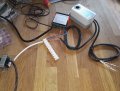
Quick update, managed to pick up an AC transformer this weekend.

You guys are correct about the pot acting as a possible input, ,because there is no 3rd middle position of actuator.
As i have it wired now, it operates as modulating (fully open/fully closed)

Must be some kind of communication with the pot, for utilising more stop points.
Im also wondering if this pot feedback is essential for operation, as the motor doesn't stop trying to turn at the limits.
Ignore wire colours and safety precautions here, just for testing...
Webp.net-resizeimage.jpg
 

Reloadron

Joined Jan 15, 2015
7,893
Well you now know it's alive.

I would set the limit switches:
"Switchover of the auxiliary switch contacts “A” and “B” as soon as the actuator reaches the respective switching positions Set the setting shafts with a screwdriver to the desired value (see section 3.2, “Rotary range and mechanical limitation”.) The angle values are valid only for the zero position of the actuator (clockwise direction). The auxiliary switches have the following factory settings: Switch A: Switchover point at 5° Switch B: Switchover point at 85°".

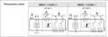
I would wire it as shown:
Siemens Damper 1.png

Siemens Damper.png

Incorporate the limit switches in your controller lines. My guess is you have a simple On/Off controller with a single set of outputs which are dry contact. If that is the case you will need to add a relay.

Ron
 

Reloadron

Joined Jan 15, 2015
7,893
Tony, there is a little more to it. Without limit switches the damper motor will drive into a dead stall. So you need to include the limit switches or use potentiometer feedback from the motor so the controller knows where the damper actually is during its travel. Also, a modulating type motor in this case is a motor which rather than an On / Off power for CW or CCW rotation uses an input of a signal like 0 to 10 Volts or 4 to 20 mA so the motor seeks a position. Using for example a control signal of 0 to 10 volts and a rotation of 0 to 90 degrees each volt of modulation would represent 9 degrees of rotation. This would be used with a controller which is PID type having a voltage output.

Anyway what we have is what Siemens calls a 3 position damper motor and I remain clueless as to exactly what the three positions are? Close, Open and Somewhere in between? I just don't get how we apply "3 Position" to this motor?

Ron
 

Tonyr1084

Joined Sep 24, 2015
9,744
Tony, there is a little more to it. Without limit switches the damper motor will drive into a dead stall.
I have a damper control motor in my garage right now, just doing nothing. It's spring loaded and returns to the closed position when not energized. It has no limit switches. Just runs to - as you say - a dead stall. It has an induction motor, and when it stalls it - for some reason I don't know of - it doesn't overheat. When power shuts down the spring slowly returns the damper to the closed position.

I'm certain there can be much more complicated systems. I even designed a system about 20 years ago. I don't know where those drawings ended up - I thin they're in my wife's office closet. The system had air returns and vents that could switch roles. Vents would blow cold air in from the floor and remove hot air from the ceiling. When heating the flow was reversed. There was even a system designed into a fresh air intake, meaning you could simply ventilate the house with fresh air through the upper vents and pull the stale air out via the floor vents. No need to even open a window. It'll probably never get built, but I do know there can be more to a simple vent than meets the eye. I shot that drawing out just to provoke a new line of thought. Using a cheap battery operated thermostat with switches that can turn on and off DC or AC controlled equipment. It really shouldn't be so complicated. It's like Engineer Montgomery Scott said about the Excelsior: "The fancier the plumbing the easier it is to stop it up." (Star Trek movie; The Search for Spock).
 
3 position damper motor and I remain clueless as to exactly what the three positions are? Close, Open and Somewhere in between? I just don't get how we apply "3 Position" to this motor?
I'm going to raise my hand. The 3'd position is manual. You can disengage the gear train and position where you want,

I think the mechanical limits are adjustable, but you HAVE TO wire the switches correctly.

Dampers mostly have a common and a close and open wire. The close and open wire straddle an AC rated capacitor. Apply 24 VAC power between com and open and it opens. Apply 24 VAC power between comnon and closed and it closes.

Put a normally closed limit contact for close in series with the CLOSE (AC power) and you have a real limit that works. Do the same with the OPEN and you have a damper that stops.

150s is a lot of time, so one might expect a modulating damper. Some systems like Carrier use the time to open for modulation and I think that's on the order of 15s.

Assume we don;t have zoneing.

You can use a regular home R-stat to turn on/off a damper. You can have relays set up for heat and cool respectively or have a mode and on control.

Some dampers are normally open, normally closed and open/close. The opposite direction may be a spring.

So, the damper can be fully on or fully off. It would likely need separate AC power. This is the norm.

The type of controller needed is more of a bang bang with hysteresis. Generic controllers have heat and cooling modes and auto-changeover. Generic controllers have a cooling cutout *engage a compressor) and a heating output (engage a heater).

HVAC controller have anticipators and some other wierd options that I will mention, Dual fuel. i won't go there now.

In the cooling mode, the thermostat controls the fan, G terminal.
The compressor turn on with Y terminals depending on stages. Yes you can play games and use positional feedback to implement stages. Stage 1 or Y1 might be 1/2 open. Stage 2 or Y2 might be fully open. They way your damper control works. But this is an HVAC thermostat. G can actually apply power to the actuator.

You;d have to build something electronic to take advantage of this.

Now, there are "spiffy" industrial controllers that will accept potentiometer feedback. This would use PID control to actually control the position of the damper. You generally can set limits. 0-100% control with a 0-10V or 0-5 V output It can also be 0-20 mA or 4-20mA with some wierdness,

Controllers that expect potentiometer input so just that. The limits are electronically adjustable, say 10% and 90%. 0-100% actually varies the output from 10 (fully closed) to 90% (fully open) or vice versa,

The PID constants, the setpoint, the mode etc set the output. The right controller will accept potentiometer feedback, Usually you find these used with valves.

So, I did show where 3 position comes from. manual, full open, full closed.

So, you can go from infinitely positionable (to a point), to on/off control.

You can with a standard HVAC thermostat or something that has a deviation output. e.g. +-10V to control stages. You can even do that separately providing all of the ducks are in a row so to speak.

But a multi-stage HVAC thermostat will have those outputs especially for cooling. Y1. y2 and y3 for 3 stage. Rc and Rh are for when heating and cooling uses a separate transformers. They are normally shorted together and are called R, C is the common terminal.

Between R and C, 24 VAC is applied. A cool relay goes between Y1 and R or Y2 and R or Y3 and R.

To use the potentiometer, the gizmo you build would have to operate on DC.

My take...
 

MisterBill2

Joined Jan 23, 2018
27,752
I'm going to raise my hand. The 3'd position is manual. You can disengage the gear train and position where you want,

I think the mechanical limits are adjustable, but you HAVE TO wire the switches correctly.

Dampers mostly have a common and a close and open wire. The close and open wire straddle an AC rated capacitor. Apply 24 VAC power between com and open and it opens. Apply 24 VAC power between comnon and closed and it closes.

Put a normally closed limit contact for close in series with the CLOSE (AC power) and you have a real limit that works. Do the same with the OPEN and you have a damper that stops.

150s is a lot of time, so one might expect a modulating damper. Some systems like Carrier use the time to open for modulation and I think that's on the order of 15s.

Assume we don;t have zoneing.

You can use a regular home R-stat to turn on/off a damper. You can have relays set up for heat and cool respectively or have a mode and on control.

Some dampers are normally open, normally closed and open/close. The opposite direction may be a spring.

So, the damper can be fully on or fully off. It would likely need separate AC power. This is the norm.

The type of controller needed is more of a bang bang with hysteresis. Generic controllers have heat and cooling modes and auto-changeover. Generic controllers have a cooling cutout *engage a compressor) and a heating output (engage a heater).

HVAC controller have anticipators and some other wierd options that I will mention, Dual fuel. i won't go there now.

In the cooling mode, the thermostat controls the fan, G terminal.
The compressor turn on with Y terminals depending on stages. Yes you can play games and use positional feedback to implement stages. Stage 1 or Y1 might be 1/2 open. Stage 2 or Y2 might be fully open. They way your damper control works. But this is an HVAC thermostat. G can actually apply power to the actuator.

You;d have to build something electronic to take advantage of this.

Now, there are "spiffy" industrial controllers that will accept potentiometer feedback. This would use PID control to actually control the position of the damper. You generally can set limits. 0-100% control with a 0-10V or 0-5 V output It can also be 0-20 mA or 4-20mA with some wierdness,

Controllers that expect potentiometer input so just that. The limits are electronically adjustable, say 10% and 90%. 0-100% actually varies the output from 10 (fully closed) to 90% (fully open) or vice versa,

The PID constants, the setpoint, the mode etc set the output. The right controller will accept potentiometer feedback, Usually you find these used with valves.

So, I did show where 3 position comes from. manual, full open, full closed.

So, you can go from infinitely positionable (to a point), to on/off control.

You can with a standard HVAC thermostat or something that has a deviation output. e.g. +-10V to control stages. You can even do that separately providing all of the ducks are in a row so to speak.

But a multi-stage HVAC thermostat will have those outputs especially for cooling. Y1. y2 and y3 for 3 stage. Rc and Rh are for when heating and cooling uses a separate transformers. They are normally shorted together and are called R, C is the common terminal.

Between R and C, 24 VAC is applied. A cool relay goes between Y1 and R or Y2 and R or Y3 and R.

To use the potentiometer, the gizmo you build would have to operate on DC.

My take...
If you had investigated the links and the manual you would see that this unit is not at all that kind of device. It is not even close to our classic damper control package. It is Siemens, a company that does EVERYTHING DIFFERENTLY, very intentionally. This is in fact a servo type system, nothing at all like the Honeywell systems and clones. With the right wiring the limit switches should be able to provide a middle position, but what I think the threadstarter wants is a setup that opens and closes a cold air supply damper to hold a room or rooms at a set temperature. And they have a temperature sensor that can command this unit to do that. It is just the matter of making a lot of connections correctly.
 

Reloadron

Joined Jan 15, 2015
7,893
It is Siemens, a company that does EVERYTHING DIFFERENTLY, very intentionally.
<Off Topic>
I was going to mention that but let it go, till now. :)

I have done quite a bit with Siemens over the years including their building technologies group. They make really good stuff and their systems work extremely well but it takes Siemens to make Siemens go and yes, that is by design. Sometimes it takes several Siemens to make a Siemens go. :)

One of the last things I was involved with before I retired was the addition of a new sub station to our facility. We brought in 13.3 KV and we had the option of 25 KV which is less costly to buy from the utility company but the cost of a 25 KV switch gear verse a 13.3 KV switch gear made 13.3 KV the better choice. The entire sub station was all Siemens equipment and again really good stuff. One feature I really liked was being able to sit at my desk and monitor the complete sub station. I could tell you where every last little amp was going, the voltages and current and the power factor. Getting it going was another story. First guy from Siemens calls in another guy from Siemens who calls in yet another guy from Siemens who is now on the phone with Germany. Finally after about 4 days the system is all up and running. The problem was a Siemens network is nothing like any other and again, their terminology made no sense. The job was quoted so it's not like cost increased but man, what a circus. Fortunately even were I not retiring this would not have been my project but we had a very nervous new facility engineer.

We also used quite a bit of their building technology to control large auto claves and again, the stuff worked great once you understood it and had it up and running. But yes absolutely, Siemens is unto Siemens.

Ron
 
@MisterBill2
I based my response on mainly post #23.

A 24 VAC motor, two limit switches (unwired) and potentiometer.

The potentiometer does suggest servo control, but if you don;t use it you get limits.
This is like some linear actuators. Limit switches only work at the absolute limits. Your supposed to use the potentiometer for feedback. It does not have to be a SERVO. The slow response usually doesn't make it a servo system.

I did a crane for a model railroad for some guy/company. The later version used positional feedback for the electromagnet crane, BUT it did not use servo feedback. I just used >some voltage for one limit and < some voltage for the other,

He made changes and didn't tell me, so the final version suffered from occasional creep because of the new "sliding contacts" in the gantry. gantry movement should have inhibited crane UP/down movement.

He also had an excellent two position loading dock sensor the first time around.

The later design sensed the presence of cargo on the dock, so a single push button could be used to initiate a Load or unload sequence.

This was also 80's technology. 1st was an 1802 programmed in assembly language. I compiled the code by hand. The second used a SBC that was programmed in BASIC.
 

Thread Starter

nebuchadnezzarg

Joined Oct 30, 2018
10
Loads of useful info here, I need to read through this again to get a better understanding!
Regarding the current project, I have a junction box to to install everything.
I think I can make this work as is..

Could someone just clarify if I NEED auxiliary switches to run this as open/close?
I cant see how to set a limit stop, the motor just keeps driving. Left the actuator powered up for about 2 hrs and doesn't overheat.
 

MisterBill2

Joined Jan 23, 2018
27,752
Form the data sheets the switches that you need are part of the motor assembly. so really they most likely are electronic limits that are easily adjustable. BUt they may also be mechanically adjusted limit switches, that part is not at all clear to me. But if you read through in the linked book, they are described. Thus, while you need them,, you already have them as part of the hardware. At least that is how I read it.
 
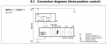
That docuement doesn't describe what the TS wants, but look at page 29. https://www.downloads.siemens.com/d...x?pos=download&fct=getasset&id1=18318#page=29

Jump S2 to 6 and S5 to 7; if the damper doesn;t stop reverse the connections (s2 to 7) and (S5 to 6)

S1 and S4 become your new #6 and #7 (where your applying power now)

The motor and damper are magnetically coupled, so no damage if it continues to run.

With an ohmmeter, you can actually figure it out by monitoring continuity between S1 and S2 and S4 and S5.
The one that's open would be connected in series with the powered wire (#6 or 7) with the damper fully open or closed.

One of the switches will open when it reaches an end point. That's the power for that direction that gets interrupted.
 

Thread Starter

nebuchadnezzarg

Joined Oct 30, 2018
10
Almost finished this project now, thanks so much to the guys that helped me out with this @MisterBill2 @Reloadron @KeepItSimpleStupid

Its not perfect and doesn't operate as i had imagined, but it does work!
I have a better understanding of basic electronics and seimens actuators now :D so will re-design this project.
Im looking at using a PID controller next to control 2x actuators with more precision.

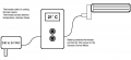
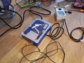
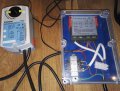
Anyway, heres the pics. I just have to glue the components down and mount the damper actuator in place...
rsz_img_20181111_083009.jpg rsz_img_20181111_083300.jpg
 

MisterBill2

Joined Jan 23, 2018
27,752
GREAT!! And for the "next project", if it is for a heating/cooling system the response is usually slow enough that you don't need a full PID control scheme, unless you are looking to move very fast or vary far. BUT Siemens experience will look good on your resume, so there could be some major value in that aspect. Thanks for letting us see how it is working out.
 
Top