Facebook
 Google
 GitHub
 Linkedin
Good day!
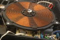
Has anyone had any experience developing wireless charging with a flat coil on the transmitter and a cylindrical coil on the receiver? It looks like it's working. With a gap of 1mm between the coils, I even got an efficiency of 57%. But with an increase in the gap, the efficiency drops significantly and after 5mm charging stops completely. Due to mechanical limitations, the gap between the coils in my project should be about 8-10 mm. And so, the questions. Is it really possible to get a working charger with such a gap? And what can be done to increase the power of the transmitter? At the moment, I am testing with TI chips (Qi 1.2), but I plan to switch to STWBC86 from ST. Thank you!
Has anyone had any experience developing wireless charging with a flat coil on the transmitter and a cylindrical coil on the receiver? It looks like it's working. With a gap of 1mm between the coils, I even got an efficiency of 57%. But with an increase in the gap, the efficiency drops significantly and after 5mm charging stops completely. Due to mechanical limitations, the gap between the coils in my project should be about 8-10 mm. And so, the questions. Is it really possible to get a working charger with such a gap? And what can be done to increase the power of the transmitter? At the moment, I am testing with TI chips (Qi 1.2), but I plan to switch to STWBC86 from ST. Thank you!