 Facebook
 Google
 GitHub
 Linkedin
New to designing circuits and PCBs. I'm working on a project and I can't seem to figure out how exactly how to do what I'm trying to do. I'm hoping one of you can give me a hand understanding the concept behind a few things I just can't seem to wrap my head around.
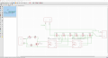
Basically, I'm designing a PCB for something that is battery powered but it's in a really tight space so it can't be removed for charging, it has to be charged in its spot. I have some 3.7v 18650 batteries that I am charging off of a TP4056. The batteries are constantly connected to their load and so I need to make a circuit that disconnects their load when the 5v is applied for charging. I'm told a MOSFET will do what I'm thinking but I can't seem to figure out exactly how.
The batteries are in groups of 3, 2 groups per each PCB. They're wired in series to get to 11.1v and in parallel with all the other groups to get me to the current I need. The plan is to charge each battery individually by being wired to the charger in parallel on a different PCB layer. I also threw in an LED as a charging indicator.
Ultimately this is a much larger design and this circuit has to be repeated 4 more times. (I need to fit this design in a pipe that is only 1.25" in diameter so it's about 7.5" total length after connecting (5) 18" PCBs.
Any advice is appreciated! Here's a picture of what I'm thinking will work: https://imgur.com/a/GRv2X
MOD: Added your image.
Attachments
-
 303.9 KB Views: 19
Last edited by a moderator:


