Why isn't centrifugal force drawn on a free body diagram?

tonyStewart

Joined May 8, 2012
239
Strain Energy is real in a way that inertial forces are also real can do work. But in the context of the question static forces are treated differently than rotational forces and thus are called fictional, just as current in an inductor might be called imaginary so that both initial and final conditions are either both excluded in a lossless system or included when calculating stored energy effects on losses.

In a lossless environment, the Strain Energy is elastic and all energy stored is returned when released.

For the inertial mass rotating about some center, it too contains stored energy previously ignored that comes to be released if one gets in the way of the moving target. But for the free-body diagram, it is neglected so that the initial conditions are still present in the end result. Thus only the linear vector forces are considered.

It is easy to confuse Real and Imaginary in electronic systems if one does not appreciate the coordinate system and the initial conditions.
i.e. We often simplify using Scalar instead of Vectors.

For Stress Forces with Strain energy, the spring stores energy ( with or without losses according to Young's Modulus) and may be termed Fictional Energy ( if restrained) but usually we consider it as a real forces as the object flexes.

For example we would not consider the Strain Energy in compressed concrete as long as it remained compressed for the forces inside a vacuum tube as long as the tube remained in tact.

But the stored Strain Energy from the tractor coupler provides real force to cars because we consider both the force to compress and release the spring and the step function of overcoming the Rolling Friction threshold.
 
Last edited:

studiot

Joined Nov 9, 2007
4,998
In a lossless environment, the Strain Energy is elastic and all energy stored is returned when released..............................................
......................For Stress Forces with Strain energy, the spring stores energy ( with or without losses according to Young's Modulus) and may be termed Fictional Energy but with Real Forces as long as the initial and final conditions are included in the same frame of reference
I really have little idea what you are talking about.

The first law of thermodynamics states that if heat is generated as a result of the compression or expansion of the spring reversibly then it equals the work done.

But the second law then says that if heat is generated it cannot all be returned to work.

This is easiest to see if we are talking about a gas spring, but it also applies to any spring.
 

tonyStewart

Joined May 8, 2012
239
I think the scholars did us injustice calling inertial force of mass " imaginary"
and the vector of Inductor and Capacitor current as "imaginary"

I would have preferred the term "potential".

This potential can be applied to DC or AC electrical systems and requires an initial external energy source with a Reactive component.

Similarily Strain Energy comes from a real Stress force but with a "reactive " or elastic component

Getting back to the Original Thread.

Stored or Reactive energy in another reference plane such as Inertial or Polar rotating mass is neglected from the "Static" vectors in the "free-body" diagram, because it is assumed to be unchanged before and after.

If there is reason to believe that inertia will change ( and satisfy the 1st law of thermodynamics) then we do not use a free-body diagram and use more complex math like
Hamiltonian or Galilean transformations from one frame of reference to another.
 
Last edited:

studiot

Joined Nov 9, 2007
4,998
If there is reason to believe that inertia will change ( and satisfy the 1st law of thermodynamics) then we do not use a free-body diagram and use more complex
It wasn't, that's why it is ignored in free-body diagrams.
Forgive me, but how are these two statements compatible?
 

tonyStewart

Joined May 8, 2012
239
Where is it inconsistent? Inertia is another frame of reference (polar) and is also (presumed) lossless and thus has no net effect in the free-body diagram for this analysis and thus NOT included.

However if there were a vertical rotating mass on an object, then withing the cycle of time, there is an oscillatory effect of the forces, within the cycle of time, but no net effect over time.

Your tractor example was an exception of Stored Energy as it is stored then released after the Rolling friction threshold is exceeded and thus is within the duration of the event being questioned. Oscillations would occur unless dampened or energy lost from friction. In your simple example, it would exert a sinusoidal force on top of the static force from the 2nd order effects of the Stored Energy in the spring from strain.

If you are unclear. Perhaps someone else can say it clearer.
 
Last edited:

tonyStewart

Joined May 8, 2012
239
I stated IF THERE IS REASON ... that inertia will change. No contradiction.

In your tractor case the applied force to the cars with a steady force of 10 mN + Rolling friction of 4 mN , nothing happens until the spring compresses to a force of 4nM then motion begins with accleration of the resulting applied force is 10 + 4 sin(ωt) with a peak force of 14 mN and a margin of 1 mN before suspect failure at 15 mN. .. due to the stored energy in the spring and the threshold for rolling friction.

But then it is not stated if the suspect failure threshold is static or dynamic ( force , duration or rise time or impulse.
 
Last edited:

WBahn

Joined Mar 31, 2012
33,315
Where is it inconsistent? Inertia is another frame of reference (polar) and is also (presumed) lossless and thus has no net effect in the free-body diagram for this analysis and thus NOT included.
How is inertia a polar frame of reference?

Your tractor example was an exception of Stored Energy as it is stored then released after the Rolling friction threshold is exceeded and thus is within the duration of the event being questioned.
????

You could ignore the friction and the issue of the inertia remains. The car (and the coupling) is accelerating and is therefore in a non-inertial reference frame. You can use the equivalence principle to transform it into an inertial frame that has a gravitational field pulling the car backward and figure out the force that needs to be added to the FBD that way (but how does that involve a polar frame of reference?). The more traditional way is to just apply Newton's Laws.
 

WBahn

Joined Mar 31, 2012
33,315
I stated IF THERE IS REASON ... that inertia will change. No contradiction.

In your tractor case the applied force to the cars with a steady force of 10 mN + Rolling friction of 4 mN , nothing happens until the spring compresses to a force of 4nM then motion begins with accleration of the resulting applied force is 10 + 4 sin(ωt) with a peak force of 14 mN and a margin of 1 mN before suspect failure at 15 mN. .. due to the stored energy in the spring and the threshold for rolling friction.

But then it is not stated if the suspect failure threshold is static or dynamic ( force , duration or rise time or impulse.
Note the nine orders-of-magnitude difference between 10 mN and 10 MN.
 

tonyStewart

Joined May 8, 2012
239
as Einstein said, it's all relative.

Inertia can be linear or circular in a polar coordinate system. (rotating mass)
Centrifugal forces are radial in a polar coordinate system. But required some tangential force to get started or change in the centre of mass of a rotating object to cause rotational inertia.

Once the wheel is rolling, we can assume for simplicity it is balanced and just has fixed rolling friction force dependant on the percentage of deflation from circular to radius or axle friction ( and mass, gravity etc. ) Obviously the force on the last car is much less than the 1st car being pulled.

The centripetal (& centrfugal) forces ( with a polar coordinate rotating mass) are excluded in freebody diagrams because we want to analyze the steady state effect.

In the case of the train, the polar coordinates are sinusoidal variations in the spring force resulting from rolling friction threshold in a 2nd order spring mass system.

We ARE interested in the result from the spring and friction , so we would not use a free body diagram here.

Make sense?

Sorry about the myopic milli Newtons. I realized that after it was too late and could not edit.
 
Last edited:

tonyStewart

Joined May 8, 2012
239
For the Thread Starter (TS).. We dont use the freebody diagram when centrifugal forces are involved. This is an oscillatory force not expected to affect the steady state, whether linear or centric polar radial forces are involved.

.... Unless the time scale is near or within one cycle of oscillation.

In Electronics we have simpler methods using vectors or frequency domain analysis or other methods simply vector impedance and many other methods.

This is how its done for waves in solids.
http://mysite.du.edu/~jcalvert/waves/mechwave.htm
There are simpler methods, but this is for the advanced which can be applied to springs, sound waves, etc.

above is only for the advanced reader.
 

studiot

Joined Nov 9, 2007
4,998
The physics and therefore the mathematics of rotational inertia is quite different from that of linear inertia.

There is, for instance, no linear analog of the term 'product of inertia'.

And let it be quite clear.

No forces should be excluded from free body diagrams if they act across the system boundary, doing so would violate the principles and conditions of free body diagrams.

Forces will only not appear if
1) They are internal forces.
2) The frame of reference has been chosen so that force does not appear.

A simple example of (2) is that when we take moments about a point, there are no moments for any force passing through that point.
 
Last edited:

studiot

Joined Nov 9, 2007
4,998
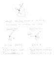
Just to be absolutely clear, here are two free body diagrams solving the same problem with and without centrifugal force.

Clearly the CF force only appears on one.

Consider a weight hanging by a string from the frustrum of a witch's hat cone.
The weight rests on the side of the cone.
Ignoring friction, the weight is supported against gravity by the tension in the string and the reaction with the surface of the cone.
Now the weight is swung so it is set in motion travelling around the surface, but not leaving it.
The weight therefore travels in a horizontal circle around the cone.

In the attached sketch I have shown two possible methods of analysis.

On the left is a dynamic analysis by Newton's laws using only the real forces that are acting.

On the right is the D'Alembert transformation to a static equilibrium analysis by the introduction of a fictious centrifugal force.

Both analyses arrive at the same results and therefore look pretty similar.

whirl1.jpg
 
Top