 Facebook
 Google
 GitHub
 Linkedin
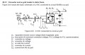
Can anyone explain why (2Cdc) appears against each capacitor in the voltage source converter model (VSC-HVDC) connected to a local ac grid?
The Picture of VSC-HVDC model is attached. Can anyone explain why 2 capacitors are used at the output of VSC converter and how this 2Cdc appears against each capacitor in the attached picture? I have also seen that in some cases (Udc/2) appears against each capacitor in VSC-HVDC model? Can anyone explain this difference?
The Picture of VSC-HVDC model is attached. Can anyone explain why 2 capacitors are used at the output of VSC converter and how this 2Cdc appears against each capacitor in the attached picture? I have also seen that in some cases (Udc/2) appears against each capacitor in VSC-HVDC model? Can anyone explain this difference?
Attachments
-
 129 KB Views: 4


