Where my mistake resides?

Thread Starter

Janis59

Joined Aug 21, 2017
1,894
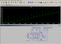
Just had one idea what I started to Spice modelling. But Spice shows it is non-working circuit. Probably one of You may tick with a finger what ought to be changed to be capable to work?
So, circuit is two 30 kV batteries, gnd in the middle point and from +30 kV down one 1nF capacitor and from -30 kV other 1 nF capacitor upwards. In point where both capacitors may meet, stays 100 nF capacitor in the H-bridge what is "rotated" 100 kHz head up and then head down and so on.
Theoretically, charges between 1 nF and 100 nF ought to divide in the manner that upper caps have 29.97 kV and bottom 100 nF half (the 1 nF and 100 nF meeting point toward GND) have 300 V. When via the diodes this charge is consumed by load (but inductance in series with load make the voltage on cap is substantially less than zero against GND), capacitor turns head down, thus the 1 nF gets kick a high voltage caps so the partial recharge of all three caps ought happen. But its not happen. So, how to force capacitors recharge? Ideas are invited. Circuit what I modelled is in attachment.

The system is needed to create the transformerless capacitive divider type "electronic transformer" for few kilowatts.
 

Attachments

Last edited:

MisterBill2

Joined Jan 23, 2018
27,193
This whole concept makes no sense to me at all. A "transformerless capacitive divider" makes no sense either.
So I see the whole concept as the initial error.
What is the intended result? If the goal is "an output of kilowatts," while the output is shown as NANOAMPS, clearly it is in the wrong direction.
So the TS needs to much better explain the desired goal.
 

BobTPH

Joined Jun 5, 2013
11,466
You seem to be saying that you can take 60KV and divide it to get 300KV and 300V. That, literally, does not add up.

Edit: And don’t assume I mean the rest of what you said is correct, I am only pointing out the most glaring error.
 

Thread Starter

Janis59

Joined Aug 21, 2017
1,894
The concept is that string of capacitors have voltages inverse proportional to capacitances at moment of first charge-up. Later, if to "drag" little bit the upper capacitor voltage, changing the lower one to contra-polar, then new charge-up to previous value ought be possible. Sure it cannot work with one capacitor and one load capacitor. But when there are two polarities, it should be possible somehow to let the AC component of load current flow via upper capacitor or other words, let process goes similarly like AC via any kind of X(C). The problem itself stays in the sad fact there are no in the markets cheap and widespread 30 kV igbt nor Mosfet nor anything else (yet Belkin produced up to 100 kV and up to 100A switches are absolutely too exotic). Therefore all the commutation must stay in the low voltage side. Factually what is needed - the 30 kV to 220 V DC-DC down-coverter for which the most of voltage load takes the capacitor. Just as the Patent author I know how to make high frequency MegaVar able several tens of kV strong capacitors for small coins with loss factor tangens 0.00003 and less. So, must to find how to make a voltage step-down.

RE""A "transformerless capacitive divider" makes no sense either."" You may convince me they teach wrong? https://www.electronics-tutorials.ws/capacitor/capacitive-voltage-divider.html .... The whole problem is to how to let upper capacitor see the load being AC not DC.

Something similar tried at least two sci article authors, but in way what is not applicable to me, most prominent is:

BHSC topology: Mihaiță Gireadă, Dan Hulea, Nicolae Muntean, Octavian Cornea (2023) A Common-Ground Bidirectional Hybrid Switched-Capacitor DC–DC Converter with a High Voltage Conversion Ratio (Energies 2023, 16(3), 1337; https://doi.org/10.3390/en16031337

Bit older but in another way was organized by Sanjeevi Thirumurugesan, Vidatronic named SC DC-DC converter (https://passive-components.eu/effic...-converters-for-battery-powered-applications/), but this also contains the switch in the high end of voltage.
 
Last edited:

Thread Starter

Janis59

Joined Aug 21, 2017
1,894
You seem to be saying that you can take 60KV and divide it to get 300KV and 300V. That, literally, does not add up.

Edit: And don’t assume I mean the rest of what you said is correct, I am only pointing out the most glaring error.
I said I get 2x 30 kV not 300 kV; and want to get out 300 V with 100x larger current. If anywhere are mentioned 300 kV, its the typo. Yepp, i find where and put the comma to right place. Sorry for lack of attention, but it not change not a yotta on principle.
 

Thread Starter

Janis59

Joined Aug 21, 2017
1,894
RE: Irving. Thank You wholeheartly, but if it shows F*** to me it will show the same to any of helpers. So, its no meaning to multiplicate circuit with false idea inside. The idea must be repaired not the naked file. Am I speaking right?
 

BobTPH

Joined Jun 5, 2013
11,466
I said I get 2x 30 kV not 300 kV; and want to get out 300 V with 100x larger current. If anywhere are mentioned 300 kV, its the typo. Yepp, i find where and put the comma to right place. Sorry for lack of attention, but it not change not a yotta on principle.
Either I misread it or you went back and corrected it, because I now see it says 29.96KV.

So your purpose is to get 300V from 60KV? You cannot do that efficiently using only capacitors.
 

MisterBill2

Joined Jan 23, 2018
27,193
This might possibly work in a theoretical world, but not in a real world.
AND, how would you propose that it could possibly be smaller than a transformer of equal power capacity, no matter what the voltagesor power level were? Certainly capacitorsand switching will cost more and be less efficient.
 

BobTPH

Joined Jun 5, 2013
11,466
I proved in another thread that lowering voltage via capacitors is exactly as efficient as any other linear regulator, i.e. the efficiency is Vout / Vin.
 

Alec_t

Joined Sep 17, 2013
15,105
Here's a reduced-power version of what I think you're looking for. C1 and C2 do the voltage division.
It may work in Spiceland, but not in the real world for handling ~kW.
1687980688817.png
 

Attachments

Irving

Joined Jan 30, 2016
5,002
I don't see how a capacitive 'transformerless' design could ever work. Sure Q = CV, so a charge Q on a 1nF capacitor @ 30kV results (allegedly) as 300v on a 100nF capacitor when connected together. But Q = I * t so to transfer that charge in must take a shorter time than transfering it out, so the current must be massive. Indeed, looking at @Alec_t simulation, I(C1) -> I(C2), though it averages only 800mA (for 300mA out), individual transfers are >10MegaAmps and the rms is 18KAmp!
 

MisterBill2

Joined Jan 23, 2018
27,193
Certainly the controls for the switches in the circuit of post #11 will need to get the timing exactly correct, and all of the switching devices must have zero response time. And in addition to there being some very high currents, the capacitors must have very low internal resistance to avoid getting rather hot. So it is going to cost more than a transformer of the same capability, and probably be larger, and worst of all it will need control hardware and software. A transformer simply needs a good mounting arrangement..
And high voltage transformers are cheaper than that kind of high voltage capacitors.
 

Thread Starter

Janis59

Joined Aug 21, 2017
1,894
This might possibly work in a theoretical world, but not in a real world.
AND, how would you propose that it could possibly be smaller than a transformer of equal power capacity, no matter what the voltages or power level were? Certainly capacitorsand switching will cost more and be less efficient.
I answered it yesterday. My Patented capacitors for 30 kV 100 kVAR to 10 MVar cost few USD per piece for 100 pF and about ten USD for few nanofarads. So, the capacitors are small and cheap.
Switching - MUST be done in the low voltage side. That is the point not under discussion. Switch in the high side may organize anyone. The transformer for 20 kV to 220 V at 10 kW cost several tens of thousands and weight near the tonn. In contrast my pre-last hand-warming wonder 120 kW 36 kV take about 0.4x0.5x1.0 meters volume and weight about 50 kg. Last masterpiece 100 kV 0.1 A for ion accelerator take 30x25x30 cm and cost slight above 100 USD if not count the enormous input of job.
So, I clearly see both Your statements are false, sorry.
 

Thread Starter

Janis59

Joined Aug 21, 2017
1,894
RE:""the capacitors must have very low internal resistance to avoid getting rather hot"". In the capacitor sciences it is called ESR, but not that is straight responsible for warming I assure. ESR source is resistance of claddings whilst warming of capacitors in 99.9999% of cases are caused by warming of dielectric. And that parameter is called tan(delta). Normally capacitors have 0.01...0.001. I have 0.00003. Will it be okay?? Sure! Its well tested in 100 MHz 5 kV 20 A ICP generator, in 60 kW 3 MHz induction melting apparatus etc etc. Up to 10 MVAR I know from own experience it warms acceptably. Dont know at GVAR and more, there probably may erect any expected and unexpected problems. But not here in the 20 kV duck-lake.
 

Thread Starter

Janis59

Joined Aug 21, 2017
1,894
But Q = I * t so to transfer that charge in must take a shorter time than transfering it out, so the current must be massive. Indeed, looking at @Alec_t simulation, I(C1) -> I(C2), though it averages only 800mA (for 300mA out), individual transfers are >10MegaAmps and the rms is 18KAmp!
Well, good argument, however network may give a short rare splashes without of any alarm. That first. But secondly, any current may be restricted by means of small chokes etc measures. So, this moment is question on general topology of circuit what must be innovative, not about small incremental upgrade of well known topologies. And yes, my Spice shows as well the any consume of energy is damn fast "needle". Even if 18 kA, the few picosec short gives just about nothing as rms. Isnt it so?
 

Thread Starter

Janis59

Joined Aug 21, 2017
1,894
Here's a reduced-power version of what I think you're looking for. C1 and C2 do the voltage division.
It may work in Spiceland, but not in the real world for handling ~kW.
Thank You for care, but completely wrong. Your circuit contains all switches in high side, and yet I have kept in the hands such switches, but my monthly salary is too short to buy even one. All switches must be in the low voltage side, therefore that circuit is not applicable to the task. Tas is to make innovative a damn cheap and small 20 kV 50 Hz transformerless step-down power source to 300 V DC for power range from 3 to 10 kW.
Okay, shall give a hint, transistors permitted may be, as an example IXFH42N60. Switches from the following page are not in the discussion, however them are qualified to work in the high side. https://www.behlke.com/gallery.htm
 

Thread Starter

Janis59

Joined Aug 21, 2017
1,894
RE: MisterBill2: <<I proved in another thread that lowering voltage via capacitors is exactly as efficient as any other linear regulator, i.e. the efficiency is Vout / Vin.>>
Hmmm. Sure it is right for brutally switched capacitive divider in AC network. But for all other possible zillion of cases ... would be nice to read the more detailed explanation in that text before take any strong conclusion. For this moment, intuitively seems that is more question of circuit topology.

For example. Take capacitive divider and set meandric generator of 300 V instead of lower capacitor. What will happen? The upper capacitor will follow and serious current from upper DC source will flow, depending on values of capacitance. So, there are no osses except the R(d-on) etc small heat fluxes.
 
Last edited:
Top