Facebook
 Google
 GitHub
 Linkedin
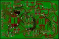
No, I;m referring to your hand-drawn CS/ wire on the PCB image. That shows that 2 slaves, the AK8963 and the PIC18F4431 MSSP SPI are using the same CS/ line. If the master 4620 is going to communicate via SPI to these two SPI slaves, each needs its own CS/. Only one CS/ can be low at a time.ME- I have hooked up the (As D/S) SPI PINs see PCB5. I have also added an 8MHz XTL xPLL = 32MHz, to the SLAVE, as I read, it needs to be faster than it's MASTER.
JY- You picked up the SPI bus OK and hooked SCK, MOSI, MISO to the correct pins for the hardware MSSP SPI peripheral on the 4431 slave BUT, you can't use the same SS/ (CS/). Each SPI slave must have its own CS/ line or you will get bus contention due to multiple slaves driving MISO.
Me- Are you referring to this line in 4431? Symbol slave_cs = PORTC.6 The SLAVE doesn't have any of it's own SLAVES, so I think this line can be removed?
The only one I see is implemented in firmware i.e. bit banging each serial bit instead of using the hardware MSSP SPI peripheral. Either way, using the MSSP hardware peripheral is probably better.JT- Yep. If I understand correctly, OSH doesn't support the hardware SPI peripheral in their library functions so you're on your own.
Me- It does have it in the library, but as there were errors, we have been testing this different method. (Perhaps Oshonsoft SPI is ok??) Probably best to carry on this way?
One master, many slaves is a better approach. The SPI design provides for multi-master BUT, you have to write your own protocol so that the various masters know when it's OK to grab the bus and start communications and deal with CS/ lines from multiple sources. It ain't worth it IMO.ME- SSPCON SSPM, can you clarify, MASTER or SLAVE?
JT-I am working on the notion that the 4431 is the SPI slave i.e. the 4620 initiates all SPI comms and drives SCK. That makes the 4431 an SPI slave and since there are multiple SPI slaves on the bus, requires that you use a unique SS/ to select the 4431 slave for comms.
ME- The initial idea was to switch the 4431 between MASTER-SLAVE, so some CODE may still be there from that idea. If you spot any I'll remove it and re-post it in #38. So only MASTER slave_cs = PORTD.2 to SLAVE PORTC.6 IN (SS)
So, onward but you do have to separate the CS/ shared between those two slaves. It will take another port pin on the 4620.
Have fun!
")