 Facebook
 Google
 GitHub
 Linkedin
Hello,
I need to store a short audio sample in flash memory, to be played back using a PWM DAC (lowpass and all) for a hobby microcontroller project and I thought about storing it as µ-law, given that it's a relatively plain sample-level algorithm.
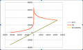
On W***pedia, it says something about companding. I did a small test: I generated a file with all sample values, converted it to µ-law (using these routines) and back to PCM and plotted input sample values vs output sample values. The thing is, the line was straight! So I thought, perhaps µ-law is not meant to be decoded before playback. I plotted compressed µ-law too (see attached image.) It looks weird. Most importantly though, if I open the µ-law file as raw data, as though it was PCM samples, the audio sample doesn't look (or sound) anything like the source material.
I don't understand what µ-law does. Where is the companding? How is it different than if one simply truncated the 16-bit source PCM material to 8 bits?
I need to store a short audio sample in flash memory, to be played back using a PWM DAC (lowpass and all) for a hobby microcontroller project and I thought about storing it as µ-law, given that it's a relatively plain sample-level algorithm.
On W***pedia, it says something about companding. I did a small test: I generated a file with all sample values, converted it to µ-law (using these routines) and back to PCM and plotted input sample values vs output sample values. The thing is, the line was straight! So I thought, perhaps µ-law is not meant to be decoded before playback. I plotted compressed µ-law too (see attached image.) It looks weird. Most importantly though, if I open the µ-law file as raw data, as though it was PCM samples, the audio sample doesn't look (or sound) anything like the source material.
I don't understand what µ-law does. Where is the companding? How is it different than if one simply truncated the 16-bit source PCM material to 8 bits?
Attachments
-
 18.6 KB Views: 14
Last edited:

")


