What did you repair today ?

cmartinez

Joined Jan 17, 2007
8,803
The name of last one does not instill a lot of confidence, MABE (MAYbe)!
Have you joined the Air Fryer crowd yet? ;)
Surprising how much cooking you can get done in them, No, or very little oil used. !
Lol! ... I hadn't realized the phonetic weakness in MABE's brand ...

I have a friend who has a dual basket Ninja air fryer and he swears it's changed his life. I'm going to give it some serious consideration. Thanks for the suggestion, Max.
 

dl324

Joined Mar 30, 2015
18,432
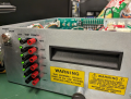
I repaired an Energy Concepts model 20500C power supply. Bought it on eBay as non-working 15 years ago or so. It was indicating a continuous overload on the 0-25V supply. Couldn't find any schematics and it appears that they used the same model number for several supplies.

Removed the SCR from the crowbar circuit and the supply started working, so I decided that I didn't need overload protection or the aggravation of tracing the circuit to make a schematic.

The display wasn't working either. It uses a couple of neat IC's that are no longer available, so I installed a cheap display with double sided tape over the hole used by the overload LED.

The variable side is good for 3A.
energyConceptsModel20500C.jpg

The order of the output terminals is goofy, but I'll live with it for now. At least the jack spacing is 0.75".
 

joeyd999

Joined Jun 6, 2011
6,362
I repaired an Energy Concepts model 20500C power supply. Bought it on eBay as non-working 15 years ago or so. It was indicating a continuous overload on the 0-25V supply. Couldn't find any schematics and it appears that they used the same model number for several supplies.

Removed the SCR from the crowbar circuit and the supply started working, so I decided that I didn't need overload protection or the aggravation of tracing the circuit to make a schematic.

The display wasn't working either. It uses a couple of neat IC's that are no longer available, so I installed a cheap display with double sided tape over the hole used by the overload LED.

The variable side is good for 3A.
View attachment 313298

The order of the output terminals is goofy, but I'll live with it for now. At least the jack spacing is 0.75".
Replace those banana jacks with some good binding posts, and you're good to go!
 

dl324

Joined Mar 30, 2015
18,432
I have a friend who has a dual basket Ninja air fryer and he swears it's changed his life.
Due to a lack of counter and cabinet space in the kitchen, our air fryer is stored in the garage on top of a pantry. Since I have to climb on things to reach it, I discovered that convection mode on the toaster oven (that has a place on the counter), was about as good as the air fryer.

And no, we don't use the toaster oven to make toast. It's much better when it's done in a toaster.

Fries in the air fryer are decent, but they take too long. That's still a job for the double basket deep fryer.
 

MrChips

Joined Oct 2, 2009
34,974
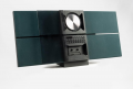
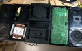
I just finished repairing and restoring a Bang & Olufsen Beosound Century 2000 Radio/CD/Cassette HiFi player.

I replaced one broken belt for the sliding window mechanism and a broken gear for the cassette drive. I replaced the two pinch rollers in the cassette drive that were in pretty bad shape.

I could not get the cassette to run and suspected that the cassette-loaded sensors were not registering. As I see it, two sensor levers for the left side record sensor and the cassette sensor were the wrong part installed at the factory. Go figure. I got that fixed with a bit of epoxy.

1707093313678.png

Bang & Olufsen Beosound 2000.jpg
 

MrChips

Joined Oct 2, 2009
34,974
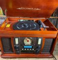
Today I repaired this Victrola 5-in-1 stereo unit. No sound.

It plays vinyl, cassette tape, CD, AM/FM radio, and AUX. Antique look with all digital controls and sound channeling.
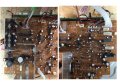
The circuit board is a pain to access and remove from the unit. All the connectors are glued together with contact cement. Why the hell was that necessary?

No circuit schematic to be found.

Victrola 600x600.jpg

Victrola circuit board 600x600.jpg

I had to reverse engineer the board. Firstly, demonstrated that the IC audio amp is working.
Found 0V on VDD to the 4-channel sound processor (e.g. digital volume controller).
Removed pass transistor supplying 9V to VDD. Transistor tested OK.
Put transistor back in and unit comes alive!

Here is a repair tip. Before dismantling a unit, take lots of pictures of every screw, cable, connector, etc. you remove.
Otherwise, it is a headache to try to remember how to put everything back together.
 

Thread Starter

Externet

Joined Nov 29, 2005
2,645
A modern 'digital' stereo receiver destroyed a speaker :mad: at full blast. Its modern digital crappy volume control encoder did not obey. Not a potentiometer, but an encoder.

Similar :
1709584025258.png

Turning it, the decibel attenuation figure did not change on the display. Opened the encoder to its guts and cleaned the gooey crap out of it. Back to operation.
 

MisterBill2

Joined Jan 23, 2018
27,834
Today I repaired this Victrola 5-in-1 stereo unit. No sound.

It plays vinyl, cassette tape, CD, AM/FM radio, and AUX. Antique look with all digital controls and sound channeling.
The circuit board is a pain to access and remove from the unit. All the connectors are glued together with contact cement. Why the hell was that necessary?

No circuit schematic to be found.

View attachment 316375

View attachment 316376

I had to reverse engineer the board. Firstly, demonstrated that the IC audio amp is working.
Found 0V on VDD to the 4-channel sound processor (e.g. digital volume controller).
Removed pass transistor supplying 9V to VDD. Transistor tested OK.
Put transistor back in and unit comes alive!

Here is a repair tip. Before dismantling a unit, take lots of pictures of every screw, cable, connector, etc. you remove.
Otherwise, it is a headache to try to remember how to put everything back together.
We have an earlier version of that bad sounding piece of junk, and while the radio and phono work, and the cassette deck plays, the CD drawer would not budge. I could hear the motor running and so it seemed that there was a drive belt problem. Evidently the CD mechanism is the very first part of the assembly process because the whole thing has to be taken apart to even touch the CD deck. And the thing has twice as many steps for dis-assembly as a notebook computer (23 pages for the notebook) . The worst part of all is that the thing cost as much as my MARANTZ 2225 receiver, but does not sound even 1% as good. with two cheap 5 inch speakers, of course not.
 

MisterBill2

Joined Jan 23, 2018
27,834
Today's effort was trying out a "Buffalo" model LS-X2.0TL "network Backup drive", from the estate of a good friend. It connects by means of a standard network cat5 cable, at least I think it does, no mention of anything special in the downloaded manual. My computer acknowledges it is connected but aside from the green light, nothing.
So really it does not count as a fix, only an effort.
 

nsaspook

Joined Aug 27, 2009
16,374
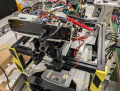
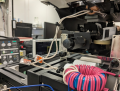
Wireless power wafer transport car from the 90's version of a semiconductor wafer transport and storage system. End of Life extension. Linear motor drivers, power supplies and HID induction power modules are all going bad. No support from the vendor so some repair procedures for the modules and some power testing setups for repairs need to be developed.
1715737378450.png
I worked on some these Daifuku systems in early 90's. Open to air wafer cassettes fit on the top. No contacts for power so no particle are generated in the clean room. You see 20 years of operation in a Class 10 cleanroom with almost zero
dust or dirt on anything inside the car.
1715739124959.png
1715737720905.png
Wireless energy pickup coils from the track. Litz wire.
1715738144512.png
Original maint manual translation from Japanese.
1715737947106.png
Prototype systems.
1715737967492.png
1715738053561.png
Motor driver top board.
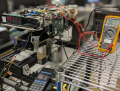
The rail wireless system outputs 140VDC so need to build a emulator (a simple current limited PS) so the coil pickups can be bypassed for bench testing. Next need to build a bench transmission rail emulator power system (a few kHz and a few hundred watts) as a source power loop so the coil and pickup boards and circuits can be bench tested after repairs. Finally some linear motor testers for that sub-system.
 

Attachments

MisterBill2

Joined Jan 23, 2018
27,834
My current repair project is neither so clean nor so complex. And not nearly as expensive or critical.
It is a HEATHKIT "SW7800" Short wave receiver that does not sound dead, but does not receive. No adequate documentation, no alignment instructions at all. And a rather unusual operation scheme, covering 900KHz to 30MHz in 20 bands.
What is unusual is that it includes a total of FOUR MC1496 analog multiplier ICs in the older 10-leaded round packages. IS THERE A current substitute if one of these needs to be replaced??
 

nsaspook

Joined Aug 27, 2009
16,374
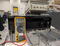
Get some basic info for building a wireless power 'transmitter'.
1715815252951.png
Wrap a few turn around the power pickup coil.
1715815301735.png
Run a few manual frequency sweeps to find the secondary tuned frequency.
1715815380995.png
About 9kHz.
1715815445738.png

Use a audio power amp to tune the primary coil a bit under load.
1715815524171.png
1715815563681.png
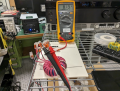
Raw DC voltage output from wireless system

1715815603797.png
We have operational (powers up) system voltage from the pickup coil using audio amp drive.
1715815741815.png
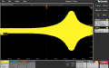
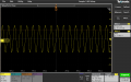
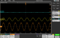
Primary coil waveforms from the Sony amp while powering the 'car' electronics. Need to optimize the power transfer parameters of the driver coil before trying to power the LDM coils for testing.
 

nsaspook

Joined Aug 27, 2009
16,374
Run a few mental calculations of what's needed to match impedances for a single loop drive coil (emulated the drive track), buy a 40X24X16 T65 toroid for the matching inductor and wind dual primary coils for the L/R amplifier channels for a power combiner with secondary power and signal sampling loops.
https://www.tdk-electronics.tdk.com/download/528846/1598c89da613db594840e493e0ffb9fe/pdf-t65.pdf

Testing the 9kHz wireless power audio matching coil for short circuit current power transfer parameters.
1715974894395.png
1715974955626.png
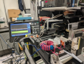
Single loop wireless power connection to 'car' and to scope for signal tuning.
1715975212427.png
1715975046454.png
Need to replace the drive loop 14 AWG stranded insulated wire with a lower loss plated copper loop bar fitted to some sort of 3D printed jig for easy attachment, alignment and removal but that's another job.
1715975085280.png
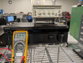
Powered car power bank voltage at @80% amplifier max power.
 
Last edited:

nsaspook

Joined Aug 27, 2009
16,374
Another tedious life extension repair job to create a procedure of future repairs for fab technicians.

Maybe 14 years ago I spec'd a replacement power modular supply module for a RTA device to replace the original separate supplies. It's so old I remember the machine running 5 inch wafers. :eek:
https://photonicmicrodevices.com/AG_Heatpulse.html
https://en.wikipedia.org/wiki/Rapid_thermal_processing
Rapid thermal anneal (RTA) in rapid thermal processing is a process used in semiconductor device fabrication which involves heating a single wafer at a time in order to affect its electrical properties. Unique heat treatments are designed for different effects. Wafers can be heated in order to activate dopants, change film-to-film or film-to-wafer substrate interfaces, densify deposited films, change states of grown films, repair damage from ion implantation, move dopants or drive dopants from one film into another or from a film into the wafer substrate.

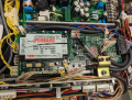
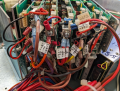
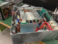
The replacement PS I spec'd and installed died and the modern TDK-LAMBDA replacement will take a month to arrive from TDK-LAMBDA so the fast alternative to rewire it back to seperate supplies. PITA but it's something that can be shipped overnight from a major supply house.

The old modular supply.
1716259571229.png

The new power supply kit installed, including new cooling fan in the kit.
1716259670707.png
1716259705900.png
Tested and ready for tech install.
Such is the job of a sometimes skillful technician. :(
 
Top