Facebook
 Google
 GitHub
 Linkedin
I am trying to get a man lift JLG T350 to work with not so good batteries. I has four 6 volts batteries giving a nominal 24 volts. I don't want it to charge the batteries, but just keep them from reaching the "Low Voltage" fault.
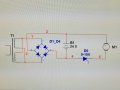
I have this huge Toroidal Transformer: Input 220V, output 0-20 / 0-20 volts, with 2.75 mm secondary copper wires that I connected in parallel (double the current). I added 5 turns of wire which gave me extra 4.16V, and my mains are 240V totaling around 26.5 volts. I added a full wave bridge rectifier using 4 Eupec power blocks DD104N16k 104 amps using the outside connectors, leaving the center pin (Thyristor tab) disconnected. (outside connectors are just diodes) which outputted 26V.
The weird thing that does not make sense at all, is when I connected the Negative clamp to the battery, the output voltage raised to 40V (just the negative!). The Lift is in the yard with the outriggers on the ground, so I thought maybe it was a feedback from ground to the non grounded transformer, but the primary is isolated from the secondary...
I also thought maybe it was just EMI voltage. However when I connected the positive clamp, the current raised to 40A and it dropped slowly to 12A as the voltage reached 30V (way above the supposed 26V), so no EMI here. If I new the voltage would increase, I would not added copper wire I would left it at 20V paralleled... Are Toroidal Transformers suppose to act weird? I retracted then lowered the outriggers all the way and them the ground: The voltage dropped to 22V and amperage increased to 60A, the diodes barely warmed up!!!
-Does anybody have any idea of why the Voltage is Increasing?
Thanks in advance!
Attachments
-
 1.3 MB Views: 9
 -
 1.6 MB Views: 10