voltages and currents calculations

Thread Starter

dukebdx12

Joined Jan 29, 2008
30
http://i32.tinypic.com/fuvww5.jpg

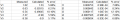
There is a grid I have done. V is voltage and I is for currents. HW3 is what I have done last week and calculated that by using a multimeter to my circuit board. The Calculated grid for Voltage is what I did today by taking V=R*I and I got the % by doing 100*(B3-C3)/B3 and for each grid. My % is way off and should be like only 5% difference and same for my currents(I=A/b). Anyone know why? My only reason is when I made the circuit and put the multimeter to it I had my + and - backwards which resulted in a negative number. Anyone know if I have made a mistake? I don't think the % numbers should be this big.
 

SgtWookie

Joined Jul 17, 2007
22,230
OK, what does your circuit look like?
Right now, I'm assuming it's 5 resistors in series:
R1: 2200 Ohms
R2: 1000 Ohms
R3: 4700 Ohms
R4: 10000 Ohms
R5: 15000 Ohms
with 19.52 volts across them.
Is that correct, or what is your circuit configuration?

And where did you read the voltages? From ground to a junction between the resistors, or across the resistors?
 

SgtWookie

Joined Jul 17, 2007
22,230
OK, since this is homework, I can't do the whole thing for ya.

Your calculations aren't taking into account the entire network, or at least the current flows in that particular section of the network. Your network gets interesting because you have two current sources, and multiple current paths.

However, I simulated a circuit that's mighty close to what you had when you were set up in the lab. Have a look.

[ETA] Updated the schematic; removed decimal points in R1, R2
 

Attachments

Thread Starter

dukebdx12

Joined Jan 29, 2008
30
yea i must have did my calculations wrong but i did what a video said was to take 100*(B3-C3)/B3 but I talked to someone that said take B3/(B3-C3) which is my HW3 for V1 / (HW3 V1 - measured V1) which = 43.7% and then do the same for I1 then take V1/I1 * 100 and it = 2.26% error which is very reasonable. Any opinions on that?
 

JoeJester

Joined Apr 26, 2005
4,390
duke,

Are you talking about rows and columns? B3/(B3-C3)?

Is the link to the video still active and can you post it?

As far as your high errors ... did you measure both voltage sources as well as each resistance before doing your calculations?

Personally I think the % error is 100 * (measured - calculated) / calculated.

Attached is your HW3 measurements compared to the calculated [actually simulated] values.
 

Attachments

SgtWookie

Joined Jul 17, 2007
22,230
OK, so where did you get the data in column C from?
It was calculated from what?

Column G has similar problems.

You need to re-visit the formulas you used for calculating those columns.
 

Thread Starter

dukebdx12

Joined Jan 29, 2008
30
jester,

that looks about right for my calculations. Unfortunately I had to turn this document in early today, so I messed my calculations up. But I was wondering how you came up with the calculated column for V and I?
 

JoeJester

Joined Apr 26, 2005
4,390
I cheated .... I used a spice simulation with perfect batteries and perfect resistors.

I'll run through the calculations using the superposition method and post the results.
 

hgmjr

Joined Jan 28, 2005
9,027
Greetings dukedbx12,

Joejester's excellent treatise showing the solution of your problem using superposition inspired me to take a stab at the same problem using Kirchhoff's Voltage Law to solve for the two loop currents.

hgmjr
 

Attachments

Thread Starter

dukebdx12

Joined Jan 29, 2008
30
wow. thankyou guys for much help and explaining. I know it had to take you guys sometime to write that out so I appreciate you doing that even though you didn't have to. My next project will be dealing with BJT (Bipolar junction transistor) amplifier. I don't know anything about it but will be learning here this week. Kind of excited as I love this class.
 

hgmjr

Joined Jan 28, 2005
9,027
wow. thankyou guys for much help and explaining. I know it had to take you guys sometime to write that out so I appreciate you doing that even though you didn't have to. My next project will be dealing with BJT (Bipolar junction transistor) amplifier. I don't know anything about it but will be learning here this week. Kind of excited as I love this class.
No problem. We are here to help if we can.

For the sake of completeness I have also put together the KCL solution to the circuit.

hgmjr
 

Attachments

Top