Voltage regulator 0-20V with current limiter 0-1A

Thread Starter

Manu Kujala

Joined Dec 21, 2016
5
Hi!

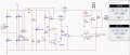
I'm a master degree student and we are trying to make a voltage regulator in this one course with specific components. We have designed the circuit for it and simulated it. It works fine in the simulation but when we made the PCB and tried to measure it, the current limitation doesn't work.. The current limiter works from approx 400mA to 1A and it should be 0A to 1A. Voltage and current are controlled by two potentiometers and the voltage information is sent to operational amplifier and op amp then controls transistors, which set the output voltage.
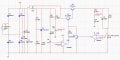
We found out that the current limiter's Q3 (you can see it in the uploaded file of our simulation picture) isn't working in the linear area. Q3 works as a current sink that limits the operation of voltage regulator, which is basically op amp 1, Q1 and Q2. So we need to bias Q3 again. The problem is the biasing though. It is kind of hard because the Vcc isn't constant in this application. Also we can't quite simulate this because simulations look OK as it is. If I make modifications then they look OK as well. So the testing is by error and it is really slow.. Plus we don't really know what we are even doing ':D
Does anyone have any good hints how to approach this problem? Here are some measurement results from simulation and from measurement:
From Q3, simulation
Vb = 0,736mV, Ib = 148uA, Vc = 4,7V, Ic = 40mA.
measurement
Vb = 850mV (so not in linear section), Ic = 60mV. We didn't/couldn't measure current because it's a PCB..
I can give more information if needed. Thanks in advance :)

BR,
Manu
 

Attachments

WBahn

Joined Mar 31, 2012
30,058
Consider what the input voltages to U1B are at 400 mA of current. How reasonable is it to expect good performance at that level. To explore if this is the problem, replace your current sense resistor with something larger, such as 1 Ω, and see if the misbehavior starts at a lower current.
 

crutschow

Joined Mar 14, 2008
34,432
So we need to bias Q3 again. The problem is the biasing though. It is kind of hard because the Vcc isn't constant in this application.
The bias of Q3 has little to do with the value of Vcc.
Why do you think it does?

Another thing I noticed is that U2 is not biased properly by R1 and R6 to regulate the voltage across it.
The voltage from the control pin to ground for the Tl431 is 2.5V when it is in regulation.
(Those R1, R6 values you have would give a theoretical regulated voltage of 170V.)
What voltage is it supposed to regulate at?

Edit: My simulation shows that the output oscillates when it goes into current limit because of the high loop gain of the current-limit circuit.
Did you not see that in your simulations?
 
Last edited:

Thread Starter

Manu Kujala

Joined Dec 21, 2016
5
Consider what the input voltages to U1B are at 400 mA of current. How reasonable is it to expect good performance at that level. To explore if this is the problem, replace your current sense resistor with something larger, such as 1 Ω, and see if the misbehavior starts at a lower current.
Thanks for your reply!
So if I understand correctly, the problem is at the U1B op amp and the current sense voltages are too small? That was our first guess as well and we did infact change the current sense resistor to 1 ohm and set the current_ref voltages for appropriate voltages. But this didn't fix the problem.. So I think it's something else.
 

WBahn

Joined Mar 31, 2012
30,058
Thanks for your reply!
So if I understand correctly, the problem is at the U1B op amp and the current sense voltages are too small? That was our first guess as well and we did infact change the current sense resistor to 1 ohm and set the current_ref voltages for appropriate voltages. But this didn't fix the problem.. So I think it's something else.
I was only suggesting that you look at that based on a quick glance at your schematic. You may well have ruled it out as being the problem.

What I would recommend next is looking at various nodes in the circuit, either with meters or, if possible, a scope, and look for which nodes change their fundamental behavior as you go from the region that is well-behaved and into the region that isn't. It might be a node that starts oscillating or it might be a node that stops changing as the settings and/or operating point change.
 

Thread Starter

Manu Kujala

Joined Dec 21, 2016
5
The bias of Q3 has little to do with the value of Vcc.
Why do you think it does?

Another thing I noticed is that U2 is not biased properly by R1 and R6 to regulate the voltage across it.
The voltage from the control pin to ground for the Tl431 is 2.5V when it is in regulation.
(Those R1, R6 values you have would give a theoretical regulated voltage of 170V.)
What voltage is it supposed to regulate at?

Edit: My simulation shows that the output oscillates when it goes into current limit because of the high loop gain of the current-limit circuit.
Did you not see that in your simulations?
Thanks for your reply!
Yeah, my Vcc was very misleading.. I meant the Vcc as the collector voltage in this case. In the textbooks it is almost always referred to Vcc.. Sorry for the mix up.
Oh, so the LM431 is also biased incorrectly.. We have made a lot of changes into the circuit and seems like I posted some of our earlier tryouts.. The R6 value should be 1kohm.
The briefing says that it doesn't matter what the regulated voltage is but it gives the steady voltage for potentiometers so we can set the voltage_ref and current_ref values with that regulated voltage to the op amps. But yes something fishy is happening when the R6 value is at 100 ohms.. sorry for the mistake. We tried to calculate that the reference voltage value should be around 19V (simulations give 19.3V)
 

Thread Starter

Manu Kujala

Joined Dec 21, 2016
5
I was only suggesting that you look at that based on a quick glance at your schematic. You may well have ruled it out as being the problem.

What I would recommend next is looking at various nodes in the circuit, either with meters or, if possible, a scope, and look for which nodes change their fundamental behavior as you go from the region that is well-behaved and into the region that isn't. It might be a node that starts oscillating or it might be a node that stops changing as the settings and/or operating point change.
Thanks again for a quick response!
We tried to look for the problem with a multimeter and we came into a conclusion that the Q3 is not biased properly. When the voltage drops over current sense resistor too much, the Vbe voltage went to 0,85V in the circuit. Also collector voltage drops to approximately 60mV so the transistor is at cut-off region. Now we need to bias it properly, but that is kind of the problem.. The collector voltage varies between approx 1V to 22V (according to simulations). So how can we bias it?
Or could there be something else wrong? We are kind of confused because the simulations give really nice results and the circuit doesn't so it is kind of frustrating as well..
 

Thread Starter

Manu Kujala

Joined Dec 21, 2016
5
So you simulations show no oscillations when the circuit is limiting the current?
It in fact does when the R6 is at 100 ohms. The R6 value should be 1kohms and then the simulations SHOULD work. If the output voltage is too samll (under 20V) then try to set the R8 resistance value to 30kohms instead of 39k. I uploaded an updated schematic.
 

Attachments

crutschow

Joined Mar 14, 2008
34,432
It in fact does when the R6 is at 100 ohms. The R6 value should be 1kohms and then the simulations SHOULD work. If the output voltage is too samll (under 20V) then try to set the R8 resistance value to 30kohms instead of 39k. I uploaded an updated schematic.
R6 has nothing to do with the current limit circuit.
I didn't ask whether it SHOULD work, I asked if you get oscillations when the circuit goes into the current limit mode.
 
Top