Wrong! Of course, they are!
However, you should discriminate between (1) ability to tune the frequency with or without influence on the oscillation condition and (2) single-element control yes/no.
it was a sarcastic reply to analog kid - (i don't like to repeat myself) i won't cange my statement about most sine wave oscillators being not entirely perfect ← this is what i have encountered so far and no matter what you say it does not change that experience.
it was a sarcastic reply to analog kid - (i don't like to repeat myself) i won't cange my statement about most sine wave oscillators being not entirely perfect ← this is what i have encountered so far and no matter what you say it does not change that experience.
Ci 139......which circuit is "entirely pefect"? More than that, in electronics, no formula is "entirely" correct...we always have to face simplifications and neglections. And, of course, there is no linear oscillator which produces "clear" sinusoidal waves.
In this context, I like the following sentence: When an oscillator circuit should be able to produce a high-quality sine wave it must be as linear as possible....and for this purpose it must contain a certain amount of nonlinearity !"
i guess i missleaded you (all) - what i kept in mind is the circuit's "nature"/ability to do something← "simultaneously" . . .
and ←that in the reasonably wide supply range and also with reasonably wide biasing elements' tolerances . . . and with not over-complex circuit layout = reasonable component count . . . ← also , with all of this , staying at a target frequency
another way to express ↑this↑ is : "At lower frequencies many sine wave generators do not lock into the Sine by default"
i rejected Colpitt's and other usually HF range ones from the comparison (at HF everything tends to become a sine - a least energy "state")
e.g. - - you probably can make/tune any "Sine Wave" osc. to produce "distortionless" output -- but it takes it's "price" - - e.g.² - takes an opamp with balanced output shoulders , a stable supply or complex frequency stabilization , etc.
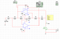
I used the GIC-resonator, but I got stuck again on how to use the JFET as VCR, when I change the input voltage the resistance of the JFET doesn't really change, and I cannot find the maximum input voltage(Vp). If someone could help.
PS: I am a first-year student, which got a project task to make this, but I have hardly any knowledge about these things.
I am a first-year student, which got a project task to make this, but I have hardly any knowledge about these things.
The meaning of "hardly any" is functionally equivalent to "none". So you have to go back and learn what you should have learned before you got to this project. The internet is probably the very last place you should go to learn basic information unless you know where to look.
BTW this site has several pages of articles on the JFET
Of course, we will help you in case of a special problem - however, here we cannot teach you how to use a FET as a variable resistance. You cannot find the information you need in the internet?? I must say - I cannot believe you.
I have used the key wording "FET as variable resistor" - and I got plenty of information....
How about showing us a schematic of your attempt to control the resistance by varying the gate voltage. Is it possible that you are applying a voltage to the Gate that is greater than the voltage on the Source. That would explain why you can't get the resistance to change. Oh, by the way you know that the change will be non-linear if you manage to do it correctly.
The attached article might help; it discusses the design of a Wien Bridge oscillator with sine wave output, tuned by a pair of JFET voltage-controlled resistors. Obviously, not a project for beginners...
How about showing us a schematic of your attempt to control the resistance by varying the gate voltage. Is it possible that you are applying a voltage to the Gate that is greater than the voltage on the Source. That would explain why you can't get the resistance to change. Oh, by the way you know that the change will be non-linear if you manage to do it correctly.
In addition to OBW0549's excellent article, here is the Siliconix (now Vishay) application note that explains the use of JFETs as voltage controlled resistors.
One of the things that is different about a JFET is that with Vgs = 0, the channel is open and there is a drain current defined in some datsheets as Idss. This means they are normally on with no bias voltage on the gate. This is really not the stuff for 1st year students to grapple with. Something does not ring true here.
The attached article might help; it discusses the design of a Wien Bridge oscillator with sine wave output, tuned by a pair of JFET voltage-controlled resistors. Obviously, not a project for beginners...
I noticed the Manhattan style dead bug construction of the VCO and can assure you this is way beyond the capabilities of a 1st year. The use of a 741 in the TS schematic is a dead giveaway that something is wrong because 9kHz is the top end of the frequency range for that part as @Audioguru has often observed.
On the other hand, grab some JFETs and start trying things with them. I did when a student and was able to design an pretty good sine/cosine generator using them in sample-and-hold circuits. Saved my employer a bundle on sin/cos pots for a raster rotation application back in the days of vacuum imaging tubes. Don't be discouraged.
Note that a FET is not the only solution for your task. You also can use an OTA (integrated circuit) or a light-dependent resistor (LDR) instead. It is always good to know the alternatives...
 Facebook
 Google
 GitHub
 Linkedin