I have a circuit that outputs an analog signal about 0 to 60mv and I need to bring that to 0 to 5V for an analog input into an Arduino. Can anyone help me with a simple circuit to provide this voltage increase?
Without knowing how fast your signal changes and what kind of accuracy/precision/stability you need here is a non-inverting operational amplifier circuit that can run off a 9V battery and will get you pretty close to 0-5V.
There are two symbols for the same operational amplifier, one showing the power connections, and one showing the amplifier connections.
You could also build a discrete transistor amplifier.
A rail-rail op amp will go very close to +5V output with a +5V supply if the load is high impedance, such as the Arduino's input. For example the MCP601 output is within 20mV of V+ with a 25kΩ load (including feedback resistor). A higher feedback resistor should let the output go even closer to V+.
The gain you need is simply the max input V divided by the max signal. Here it's 5V (Aurduino input) over the signal 60mV.
That's 5 / .06 = 83.333
Now here's the thing: you do NOT want the signal to go all the way to the 5V.
Why? You will end up not knowing if the signal is near 5V or over 5V due to some failure or some unexpected condition. And to get to 5V you need a supply greater then 5V so it's expensive.
So reserve 5 to 10% of the range for overhead. That cuts the gain you need from 83.3 to 80 or 75. That's STILL a pretty large gain (nearly 40dB) so you do have to be careful picking an amp if the signal isn't a DC.
Also, DC offset and drift is an issue as your signal starts off so small. Offset can be calibrated but drift can't, so you need a low drift.
I appreciate all the inputs to this question and it seems I should have provided a bit more information on what Im doing.
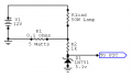
Im using a circuit similar to the one in the attachment to output the voltage across the sense resistor in a solar panel circuit. I want to be able to track the current output of the solar cell over time and varying conditions. In my case the voltages and current are different than shown in that circuit. At max output I read only 60 mv across the resistor. My assumption is that the signal changes would be relatively slow and I would like the output from the Arduino to resolve about 0.1V. I would be using a 9V battery as the power source.
I read that the zener diode in the circuit will limit the output voltage to around 5V so I shouldnt have to worry about over voltage conditions to the Arduino.
Does this additional information add any new considerations or am I ok in going with the TLV2371IP amplifier circuit Antonv suggested.
It should work. I agree with ErnieM: it would be wise to make the top of your range less than 5V so that you know you haven't maxed out some unknown reading. So the 82K resistor could be a 75k one so that 60 mV will give you 4.6 V.
Are you using the Arduino to read any other analog voltages? If so, you might have to add a 0.1 uF cap across the Zener just to help your signal accuracy when switching analog channels. I am not familiar with the Arduino's analog inputs but this is true for devices like PICs.
I will order the TLV2371IP but was wondering if something like an LM358 would work as well. I'm aware that it is a dual with a different pin configuration but operationally, will it work.
Thanks,
Tom
The LM358 could work, especially since its input voltage range includes ground. It does not have a rail-to-rail output so if powered from 5 V it won't be able to swing to 5 V but if you power it from your 9 V battery it can swing to 5 V and beyond. You will have to find a way to prevent that.
The one benefit of a rail-to-tail amp is that you can power it from 5 V which prevents out from exceeding 5 V at the output.
the LM358 is my standard op amp of choice for most thing but the maximum voltage you will get out with a 5V supply is around 3.8V, so you would have to adjust the gain resisters to allow for that. a rail to rail op amp like the ones suggested will give you a better range. I have used the TS912 op amp before which is rail to rail and has the same pinout as the LM358

 Facebook
 Google
 GitHub
 Linkedin