Visual led indication of data or voltage on can bus

Thread Starter

ToreanPW

Joined Apr 28, 2024
3
I will start with the fact that I have little to know knowledge of building circuits. I am in fact looking for someone that is willing to essentially draw me a wiring diagram and even better list of parts needed.

I am building a breakout box for an automotive OBD2 DLC. What I am wanting to do is make a visual indicator of voltage presence on can and lin busses. The idea is if there is no voltage I can wiggle harnesses and see it "turn on" or alternatively un plug a module and see the buss come on. Any actual testing of what is on the network will be done with a lab scope. I am hoping to have an LED for each pin of the DLC to watch for activity. I am not even against just having an led that is on when there is voltage present or if it is possible just on when voltage is between 1 and 5 volts. I would assume that what is used for can high and can low can be adapted for lin bus just need to change voltage levels, but as I said I have very little knowledge of the building of circuits.

Thank you for any help.
 

Irving

Joined Jan 30, 2016
4,088
Welcome to AAC

What you ask is entirely possible, yet can be done in many different ways. However, I'm not sure what you mean by " can and lin busses ". Standard ODB2 CAN connection is pin 6 and 14, plus power and ground. There is no LIN as by default any LIN busses are accessed via the main CAN bus CAN/LIN gateway (usually the dashboard). Also the CANBus on the OBD2 connector may not be the actual Bus that modules are attached to, but one for diagnostics that accesses the real Bus via the gateway but has no physical connection to it.

That aside, indication of CAN Activity is arguably more useful than simply showing CAN Voltages, as a voltage can be present due to a short which prevents CAN traffic. Ideally you need both. Also, CAN Bus is about correct differential voltages between the two bus wires (A - B) as well as an in-spec common mode voltage (A+B)/2 so simple voltage at a pin may not help. Of course all these parameters can be measured and validated at the actual CAN device interface though that is harder as there is little commonality between manufacturers for CANBus physical connections to the modules.

Maybe you can clarify exactly what physical connections you are addressing if not the basic ODB2 connector?
 

Thread Starter

ToreanPW

Joined Apr 28, 2024
3
1714933478705.png

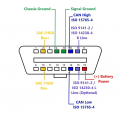
I was planning on an LED for each of the 16 pins minus 4 and 5 as they are grounds. The idea was as/if they add things in the future or if there is a short I would have a quick indication of this. Often there aren't even pins in the blank ones so I may just have the LEDs connect to ground on a switch, or omit them until they are used.
Pin 2 and 10 are SAE J1850 which can be VPW (max 7v) or PWM (5v). Pin 7 and 15 are K and L line which are ISO 9141-2 max 12v. I believe typically the can high and low 6 and 14 are directly on the network allowing labscope diagnostics right from the dlc.
As for the LEDs just a representation of voltage present that is fine as all actually testing or monitoring will be done with a labscope.
 

Irving

Joined Jan 30, 2016
4,088
Sorry, missed your response on this...
When you say 'a representation of voltage present' on a pin, do you anticipate this being greater than some minimum DC voltage (low duty-cycle signalling might show as 'no volts') or something like grounded, DC voltage > X volts, signalling (eg CAN/PWM/etc). Can you be more specific about the indication, and whether this is all pins (except those expected to be ground) or only those designated.
 

Ian0

Joined Aug 7, 2020
10,286
If you want a simple go/no-go indicator, just put an LED with a series resistor between CAN+ and CAN-. It will illuminate whenever there is data on the bus. Use the highest value resistor than gives adequate brightness as it may upset the termination of a properly terminated bus.
There should be about 40mA through each 120Ω termination, so if you keep to 10% of that it probably won't cause any problems and 4mA will adequately light an LED.
Alternatively, if you have access to the terminator, you can replace it with it by a 220Ω resistor and an LED in series with 150Ω.
The bus won't be completely perfectly terminated, but is unlikely to get into any trouble.
 
Top