 Facebook
 Google
 GitHub
 Linkedin
Hello,
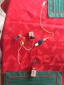
I have been working on a science fair project for a considerable amount of time with a lot of setbacks. The goal of our project is to light up an LED with vibrations, and we are doing that with a vibration sensor connected up to a sensor board (Smart Charge) that is wired up to a 9v battery and wires (signal output and signal ground) going into SMAKN® LM358 100 Gain Signal amplification module Operational Amplifier DC5-12V. I also have another 9v battery going into the Op-amp and the LED (output) wired into it too. My questions are: Is this wired right? and the potentiometer is not reading an output other than the same voltage I input. Can you explain why this is happening and not working correctly? What I want to happen is that when the vibration sensor senses vibrations the sensor board sends a signal to the op-amp and lights up the LED.
I attached an image of how I have it wired. Please verify that it's wired right?
Data Sheets:
Thank you and if you know anything that can help, please comment!
I have been working on a science fair project for a considerable amount of time with a lot of setbacks. The goal of our project is to light up an LED with vibrations, and we are doing that with a vibration sensor connected up to a sensor board (Smart Charge) that is wired up to a 9v battery and wires (signal output and signal ground) going into SMAKN® LM358 100 Gain Signal amplification module Operational Amplifier DC5-12V. I also have another 9v battery going into the Op-amp and the LED (output) wired into it too. My questions are: Is this wired right? and the potentiometer is not reading an output other than the same voltage I input. Can you explain why this is happening and not working correctly? What I want to happen is that when the vibration sensor senses vibrations the sensor board sends a signal to the op-amp and lights up the LED.
I attached an image of how I have it wired. Please verify that it's wired right?
Data Sheets:
- https://www.smart-material.com/media/Datasheets/SMARTChargeInstructionsV1 2.pdf
- https://doc-14-98-apps-viewer.googl...0783794&hash=elpuko10fsuhhe20vb9pb1resma5qolh
Thank you and if you know anything that can help, please comment!
Attachments
-
 15.5 KB Views: 14


