Very basic question about half bridge transformer flux saturation

Thread Starter

SiCEngineer

Joined May 22, 2019
442
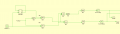
I am designing a power supply that uses a half bridge to generate the AC from DC input. I won't get into the control algorithm but it is a kind of hysteretic control / frequency hybrid. I am looking at the half bridge switching waveforms and intuitively I am unsure whether in practice there would be any issues. I will attach them to this thread.

Would the transformer saturate in this case? I am unsure if my scope simply has the switching waveforms connected the opposite way they should, but even so - if the upper MOSFET is on for a shorter amount of time (lower duty) because of hysteretic action turning both switches OFF, and then resumes switching - will the transformer saturate?

My basic idea is that the flux you put into the transformer must be taken back out - but with these waveforms this would not be the case...

But then again, so how does hysteretic mode work? Is there a way to ensure that the bridge switches always switch at 50% duty as expected?
 

Attachments

MisterBill2

Joined Jan 23, 2018
18,179
The two points are simply the upper and lower bridge gate driver waveforms. They are triggered OFF when the target voltage is reached, causing sometimes the HB waveforms to have less than 0.5 duty cycle.
Unfortunately R5 assures that the current in opposite directions will not be the same. It may be that the difference that you are seeing is due to that resistance. My guess is that the resistor is there to reduce a current inrush, but possibly there is some other reason that I have not discovered. Certainly there is a need to avoid non-symetrical flux buildup in a transformer. So while the voltages triggering the turn-off may be the same the time may not be the same.
Other than that, the design looks similar to one that was published in "QST" magazine a while back. The author provided quite a bit of discussion on the design of the transformer to avoid several serious issues.
 

Thread Starter

SiCEngineer

Joined May 22, 2019
442
Unfortunately R5 assures that the current in opposite directions will not be the same. It may be that the difference that you are seeing is due to that resistance. My guess is that the resistor is there to reduce a current inrush, but possibly there is some other reason that I have not discovered. Certainly there is a need to avoid non-symetrical flux buildup in a transformer. So while the voltages triggering the turn-off may be the same the time may not be the same.
Other than that, the design looks similar to one that was published in "QST" magazine a while back. The author provided quite a bit of discussion on the design of the transformer to avoid several serious issues.
The R5 there is just to allow the simulation to run and stop throwing a simulation error to do with the capacitors giving a state/source dependence. It is only 10mOhms.

I have tried before to find the QST magazine article that you reference - but I cannot seem to find the correct issue / access it.
 

MisterBill2

Joined Jan 23, 2018
18,179
The R5 there is just to allow the simulation to run and stop throwing a simulation error to do with the capacitors giving a state/source dependence. It is only 10mOhms.

I have tried before to find the QST magazine article that you reference - but I cannot seem to find the correct issue / access it.
TRy ading an identical resistor in series with the other capacitor. Symmetry is fairly important in this case, I think.
 

Thread Starter

SiCEngineer

Joined May 22, 2019
442
Okay, I did that and it didn't work. But I think I have found out what is happening.

Without getting into the control system too much, one aspect is to switch between two switching frequencies, a higher value and a lower value. I have attached a schematic which shows the basic way I do this. I thought using an XOR gate would mean that only the 300kHz or the 600kHz signal will pass- but obviously, sometimes, as you can see from my other results that sometimes both the 300kHz and 600kHz pulse pass. I believe the error is within the XOR logic gate. But I am unsure how to fix this to ensure that only one of the pulses passes?

The pulse is basically a control signal which triggers which switching frequency to select. Also at the moment the AND gates at the end are just ANDed with a constant 1, they are used in logic elsewhere which isn't pertinent to this issue at the moment.

Have you any advice to stop both signals being passed?
 

Attachments

Top