Vbe temparature compensated circuit working....

Thread Starter

Himanshoo

Joined Apr 3, 2015
265
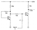
The following circuit is a Vbe temperature compensation circuit..The collector is drawing 1mA constant current….


query : The voltage drop at collector of Q1 transistor would be one diode voltage drop above ground..(as per text)

Since Q1 is connected in feedback resistor bias configuration…and the equation to find out Vc is(Vc=Vcc-IbRb-Vbe)…

only if we ignore Ib then only Vc_Q1 would be equal to 0.6 V ..is it advisable to neglect base current…??
 

Attachments

MikeML

Joined Oct 2, 2009
5,444
Lot going on in this little circuit... My R2 optimized to get best stability of V(C2) over this temperature range with 2N3904s...
203.gif
 
Last edited:

#12

Joined Nov 30, 2010
18,224
Wow! 4.4 millivolts across 130 C
about 1 twentieth of a percent of Vout.
That's really good for 2 transistors.
 

Thread Starter

Himanshoo

Joined Apr 3, 2015
265
How much does it rely on matching between the two transistors?
does base current of Q1 should be involved in deciding thermal stability of this circuit or it should be neglected..?I mean it in reference to post 1
 
Last edited:

MikeML

Joined Oct 2, 2009
5,444
does base current of Q1 should be involved in deciding thermal stability of this circuit or it should be neglected..?I mean it in reference to post 1
Himan: Since it changes by a factor of ~2 (blue trace in the sim), then I don't see how you can ignore it...

WBahn: Here it is with two radically mismatched transistors (both are Si, however).

203c.gif

Again, there is some value of R2 (close to 10K) that does the best job of minimizing the variation of V(C2) vs temperature (Yellow trace, R2=9.6K), so the analysis of how this circuit works cannot ignore the current through it (base current of Q1). I would say that this compensator would work well as long as Q1 and Q2 are in intimate thermal contact.
 

Thread Starter

Himanshoo

Joined Apr 3, 2015
265
Wow! 4.4 millivolts across 130 C
about 1 twentieth of a percent of Vout.
That's really good for 2 transistors.
Himan: Since it changes by a factor of ~2 (blue trace in the sim), then I don't see how you can ignore it...

WBahn: Here it is with two radically mismatched transistors (both are Si, however).

View attachment 84676

Again, there is some value of R2 (close to 10K) that does the best job of minimizing the variation of V(C2) vs temperature (Yellow trace, R2=9.6K), so the analysis of how this circuit works cannot ignore the current through it (base current of Q1). I would say that this compensator would work well as long as Q1 and Q2 are in intimate thermal contact.
You are right ..but my effort was to find the collector voltage of Q1 i.e Vc_Q1 and we can find it by the equation------->Vc=Vcc-IbRb-Vbe .......since the text says that Vc is one diode drop above ground...so solving the equation we can find out Vc....but problem comes with Ib ...There is no issue in finding out Ib....but the problem is that to find Ib we require current gain of Q1 (beta)..which is unknown to me....Thats why i thought may be its relevant to drop out Ib for the moment to find out Vc ...though that is wrong conceptually...
 

WBahn

Joined Mar 31, 2012
32,872
The statement that the collector of Q1 is one diode drop above ground implies two things. First, for this statement to be true, the voltage drop across the 10kΩ base resistor must be small enough to be negligible. Second, the value of "one diode drop" must be sufficiently constant so as to be meaningful. In the strict sense, neither of those statements are true -- there is some voltage drop across the base resistor and the Vbe of the transistor is not constant as it varies with both current and temperature. The real question is whether both of those statements are "true enough" for the analysis you are doing. If you are looking for a close estimate of what the output is, then it is probably close enough. You can assume a reasonably low value of beta and pick two different reasonable values of Vbe and see if they yield results that are close enough for your purposes. But if you are looking for how the circuit behaves with temperature or with load,, i.e., how good its regulation is, then those assumptions are probably not good enough because it is changes in those parameters that cause changes in the output.

Edit: lots of typos
 
Last edited:
Top