variable time delay using 555 timer

Thread Starter

Bilnigma

Joined Mar 10, 2008
11
hi
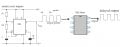
i am trying to create a clock pulses to a device, using the 555-timer astable mode. i also want to be able to delay the pulses coming from the output of the first 555 timer by a cycle or few cycles.
i dont know how to make the circuit. since the delay will be a function of R and C, then i can have a variable resistor to change the delay. i have attached a rough diagram to illustrate my point (the output of the second timer is delayed).

help is appreciated. :)
 

Attachments

Wendy

Joined Mar 24, 2008
23,415
OK, are you trying to create a phase difference between the 1st set of square waves, or stop the the 1st timer from oscillating for a few cycles upon power up? I have several thoughts on the subject, but I'm not sure what you're trying to accomplish.
 

Wendy

Joined Mar 24, 2008
23,415
So what would be the ideal phase shift? 90 degrees? I remember early CPU's needed something like that for proper operation. If it is around 90 degrees you don't really need a monostable. Soon as I draw my idea up I'll post it, but basically an RC feeding a 555 as schmitt trigger.


You could also use a 556 (dual 555) for this.

There are also a lot of other ways to do this. For example, you can also use a counter to create exactly 90 degrees phase shift.
 
Last edited:

Thread Starter

Bilnigma

Joined Mar 10, 2008
11
i just modified my design, i think it will work better if the delay is in cycles not in phase (which is like u suggested, upon power up). i can work with the phase angles but now i c cycles can be easier.
u mentioned if i meant delay cycles on power up... is it possible to adjust the cycles with power on? if that is possible, delaying cycles is my best option. however, if it is not possible, my best option will be to use phase difference.
the angle u mentioned will then have to be 180 degrees.
sry for the added complications, any circuit that can perform any of the two functions will suffice. thanx :)
 

Wendy

Joined Mar 24, 2008
23,415
OK, I am officially confused. But I will give it my best shot. The circuit I drew will vary the phase angle of the second square wave, add a variable resistor in the RC circuit and it can be variable.

Pin 4 on the 555 is an on/off digital input, which can be used to remotely turn off the 555. This could be used to delay the 555 oscillator. I have never built the second concept, so I don't know how it would work, but here is an example...


Thread Starter

Bilnigma

Joined Mar 10, 2008
11
:) i think u just solved my prob, as long as the phase can be changed i'm good to go. i'll rmb to keep u posted on the circuit when i implement. thanx
 

whywhy68

Joined Jun 11, 2008
13
OK, I am officially confused. But I will give it my best shot. The circuit I drew will vary the phase angle of the second square wave, add a variable resistor in the RC circuit and it can be variable.

Pin 4 on the 555 is an on/off digital input, which can be used to remotely turn off the 555. This could be used to delay the 555 oscillator. I have never built the second concept, so I don't know how it would work, but here is an example...


i also interested in making a astable squave wave output with varying phase angle.. which circuit wrks ? left one or right?
 

bloguetronica

Joined Apr 27, 2007
1,541
Nice schematic, Bill! There are other designs for 50% duty cycle, but I never thought of that one. That is a very intelligent and yet simple design.
 

Wendy

Joined Mar 24, 2008
23,415
The two schematics I drew should delay the startup of the oscillator for a few cycles, while the first one will create two identical square waves with a shift in phase.
 

Audioguru

Joined Dec 20, 2007
11,248
Hi Juan,
The 555 push-pull circuit produces push-pull pulses that are not a good square-wave and they are not a modified sine-wave.
They need to have an additional circuit to make them square and to gate them into a modified sine-wave.

Common Cmos logic gates have been available for at least 30 years.
 

JUAN DELA CRUZ

Joined May 27, 2008
121
Thanks Audioguru...:)

The 555 push-pull circuit produces push-pull pulses that are not a good square-wave and they are not a modified sine-wave.
Yes, you're right. But I need to make an Osc. by 555 Timer (Bipolar) that can be substitute for Cmos Osc. (CD4047..w/c is also tricky to find here in my country).......I'm planning to make another MS-wave inverter w/ stable voltage output w/out the use of Cmos ICs.

They need to have an additional circuit to make them square
You mean an op-amp??..or another 555 timer ckt.???

and to gate them into a modified sine-wave
Yes, I'll use CD4025 (I hope it's now available here in our province)

I'm limited in components, just 555/556 (bipolar) Timer & op-amp/comparator

I've thought of an idea of making an MS-wave inverter w/ stable output
by using 556 DUAL timer (bipolar ) as the Osc.
& LM324 QUAD OP-AMP.

I'll post my schematic diagram in a few days.

Thanks.
 
Last edited:

Audioguru

Joined Dec 20, 2007
11,248
A 555 can have a fairly square waveform if one of its timing resistors has a value that is much higher than the other one. Its output high and low are good enough to drive a CD4025 Cmos gates IC.

Since the output current of the 555 is zero then nearly anything (a transistor, a logic inverter or a logic gate) can be used instead of a second one. The unused 3rd logic gate in the CD4025 can be used.
 

JUAN DELA CRUZ

Joined May 27, 2008
121
Thanks for reply.

A 555 can have a fairly square waveform if one of its timing resistors has a value that is much higher than the other one. Its output high and low are good enough to drive a CD4025 Cmos gates IC.
In my ckt, 555 timer will produce an sawtooth wave.......
.....and an Op-amp to vary the input to CD4025 Gates to obtain stable voltage output, just like my previous ckt w/ 555 (Cmos) & decade counter IC (w/c is very tricky to find here in our province).

Another 555 astable ckt. producing 100Hz w/ an op-amp to vary the other input of NOR gates (just like the output of PIN 13 of CD4047).

The unused 3rd logic gate in the CD4025 can be used.
I will be using the remaining NOR gates for Low battery cut-off ckt.

I'll post my schematic in few days.......:rolleyes:

Thanks.
 

Wendy

Joined Mar 24, 2008
23,415
I'm not sure what you're trying to do, and this should be on a new thread, but wouldn't this work better?


Seriously, if we continue this discussion it should be on a fresh thread, forum rules you know...

OK, I've reread your post, I'd use the invertor function of this 555 circuit, it is basically an inverting Schmitt Trigger. You might run into timeing issues, but it would basically work. I won't say anything else here, but if it is brought up on another thread I'll show how I'd do it...
 
Last edited:
Top